The is a modified Arduino Nano, that was built to controll servo motors. This is an open source board, with all the files needed for manufacturing. You may also freely modify the design.
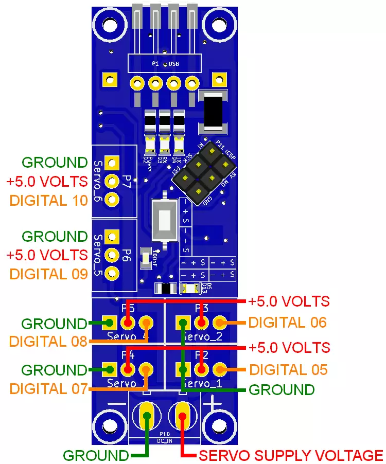
The contains an ATmega328P microcontroller so you can program it just like an Arduino Nano using the Arduino IDE environment. It has a micro USB port, which is compatible with mobile phone USB cables. It was designed to easily control servo motors, and it has standard mounting holes for M2 screws. You can connect any type of servo motor to it. The important thing is that they must have the same voltage requirement, because the motor power is supported by connecting an outside power source to the 2 pole terminal (GND and Vcc from left to right). The servo motor pins from left to right are: GND, Vcc and PWM (these are white JST sockets you can see on the module). The connected servo motors are numbered from 1 to 6. Controlling servo motors from 1 to 6 happens from the D5 to D10 pins of the ATmega328P.


|
Download files for manufacturing
|
|
Datasheets
Tutorials
Examples
|
Specifications:
- IC: ATmega328P
- Clock Speed: 16 MHz
- Flash Memory: 32 KB
- SRAM: 2 KB
- EEPROM: 1 KB
- USB support provided by a CH340G USB to serial chip:
- Micro USB (compatible with mobile phone USB cables)
- Connection to the Ozeki HUB Controller
- Power supply from USB (5V)
- 500mA resettable fuse
- Status LEDs: power, TX, RX, D13
- Servo motor power supply connection terminal
(GND and Vcc from left to right) - 6 servo motor connections
(GND, Vcc and PWM from left to right) - Can be screwed on an Ozeki Matrix Board
- Product dimensions:
2.40in.[60.96mm]×0.80in.[20.32mm]
Pinout of the :

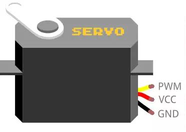
The pinout of the Servo motor:
The servo motor has three leads. The color of the leads varies between servo motors, but the red lead is always 5V and GND will either be black or brown. The other lead is the control lead and this is usually orange or yellow.

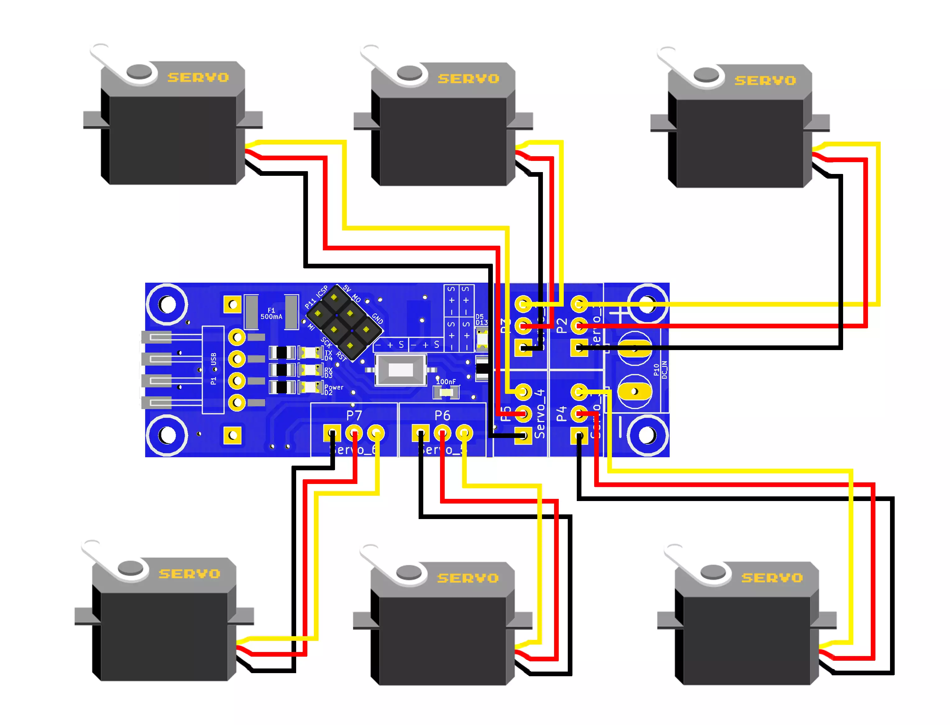
Wiring:
Connect the servo motors to the Ozeki Servo Module as shown below. Before wiring the servo motors to your Ozeki Servo Module we suggest to solder a JST header strip to the following 3 pin count connector, as you can see in the image above.

Program codes
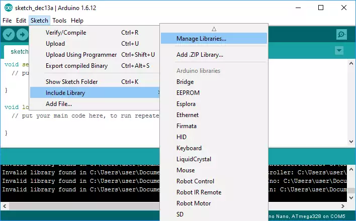
These codes are based on functions included in 'Servo.h' so to test these examples you will need Servo.h which is defaulty included in the Arduino IDE libraries. If it is not included then the compiler will through an error message. In this case you simply need to download Servo.h from the Arduino library list which you can find inside the Arduino IDE. To do this please select 'Sketch/Include Library/Manage Libraries...' from the top menu as you can see in the picture below.

A code that moves servo motors (maximum 6)
The code moves a maximum of 6 servo motors. It can move any type of servomotor if you provide them the proper amount of energy. The servo motors are indexed from 0 to 5. First it turns them counterclockwise one by one from servo 0 to 5 then it turns them clockwise from servo 5 to 0 and repeats this sequence infinitely.
Downloadable code:
Example code (.zip)Source Code 1 - Arduino example code for moving six servos counterclockwise and then clockwise#include <Servo.h> Servo servo[6]; int pos = 0; int n; void setup() { servo[0].attach(5); servo[1].attach(6); servo[2].attach(7); servo[3].attach(8); servo[4].attach(9); servo[5].attach(10); n = sizeof(servo) / sizeof(servo[0]); } void loop() { for( int i=0;i<n;i++){ inc(i); } delay(100); for( int i=n-1;i>=0;i--){ dec(i); } } void inc(int pin){ for (pos = 15; pos <= 160; pos += 1){ servo[pin].write(pos); delay(15); } } void dec(int pin){ for (pos = 160; pos >= 15; pos -= 1){ servo[pin].write(pos); delay(15); } }
Video 1 - Moving 6 servos with using the code above
A code that moves 2 servo motors
In this example we move SG90 and MG996R servo motors which are the most popular and cost effective servos. However this code is capable to move any other servo motor if you provide the necessary power through the Ozeki DC-DC Converter. First it turns the servos counterclockwise one by one then it turns them clockwise and repeats this sequence infinitely.
It is almost the same as the 6 motor code you can see above.
Downloadable code:
Example code for two servos (.zip)Source Code 2 - Arduino example for moving 2 servos counterclockwise and then clockwise#include <Servo.h> Servo servo[2]; int pos = 0; int n; void setup() { servo[0].attach(5); servo[1].attach(6); n = sizeof(servo) / sizeof(servo[0]); } void loop() { for( int i=0;i<n;i++){ inc(i); } delay(100); for( int i=n-1;i>=0;i--){ dec(i); } } void inc(int pin){ for (pos = 15; pos <= 160; pos += 1){ servo[pin].write(pos); delay(15); } } void dec(int pin){ for (pos = 160; pos >= 15; pos -= 1){ servo[pin].write(pos); delay(15); } }
Video 2 - Moving 2 servos with the power coming from the Ozeki DC-DC Converter
Other modules
All of the Ozeki Processing Modules have ATmega328P or ATmega2560 microcontrollers integrated. Ozeki Modules can be connected to eachother like pieces of blocks. The connection is provided through USB to each module. They have M2 screw holes to give you an option to screw them on an Ozeki Matrix Board.
AutoConnect Link
If Ozeki 10 is running on your computer (such as on a Raspberry Pi) and you have plugged a microcontroller to it than Ozeki can be set to find serial devices on windows/linux and place them into a connection list so you can interact and control them through the software GUI.

 Sign in