
 Sign in
 Relay board
|
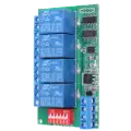
With this 4-channel relay interface board you can control various appliances and other equipment with large current. It allows you to control each channel with 6 commands including open, close, momentary, self-locking, interlocking and delay. On this page, you can see how to connect this relay board to the computer and control the channels using the Modbus RTU protocol. |
Connect the relay board to PC
To control the channels on the board, you need to connect the board to your PC using an USB to RS485 converter. It provides easy connectivity between the PC and the standard communication port. The Figure 1 shows how to connect it to the board. Then, on the board you need to turn on the A5 switcher. Turning on A5 means that the board wait for Modbos RTU type of commands (and not AT). Finally, attach it to your computer.

Specifications of the board
There are many relay board exists such as 2-channel, 4-channel, 8-channel and 16-channel ones. Most of them need the same voltage and support the same operating modes, but the other parameters may be different from this one. Due to this, the following specification applies to this 4-channel relay board only.
| Specification | Value |
| Power supply | 12V DC |
| Operating current | standby/11-13mA, 1-channel/44mA, 2-channel/77mA, 3-channel/110mA, 4-channel/140mA |
| Operating mode | open, close, momentary, self-locking, interlocking, delay |
| Control mode | RTU and AT |
| Maximum delay | under AT instruction mode: 9999s, under RTU: 255s |
| Maximum connection | under RTU instruction mode, it supports 32 devices parallel connection |
| Maximum load | AC 10A/250V, AC 10A/125V, DC 10A/30V, DC 10A/28V, DC 10A/12V |
Setting up the relay board
You can set the slave ID of the device using the A0-A4 switches found on
the board. This allows 32 different IDs to be set. The numbers below the
switches are added together and the result will be the identifier of the device.
So, if you would like to set the slave ID to 1, you need to turn A1 on and off the
others. To set ID to 2, turn A2 on and off the others. To set the ID to 3, turn A1
and A2 on and turn off the others and so on.
With switch A5, you can customize the instruction mode between
Modbus RTU (if the switch is on) and AT (if it is off).
The examples of this guide use Modbus
RTU protocol commands. To try them, please turn A5 on.

The serial port settings of the relay board can not be configured. These values are predetermined by the manufacturer. In Table 2 below, you can see what setting values should be used to communicate with the device (called slave). These values of another manufacturer's relay board may be different.
| Parameter name | Value |
| Baud-rate | 9600 bit/s |
| Parity | Even |
| Data bits | 8 |
| Stop bits | 1 |
About Modbus
Modbus is a serial communication protocol that uses command and response frames to implement the communication between one master and many slaves. Only one master is connected to the bus, and one or several (247 maximum) slaves are also connected to the same serial bus. The Modbus communication is always initiated by the master. There are several versions of Modbus protocol that you can find more information about under Connections. The master can write the register values of the slave device and get them by sending a command message. The slave device sends back a response one that contains the requested information.
Connect more relay boards to master
To connect more slaves to master, you need to wire them like the Figure 3 shows. You can connect up to 32 slaves in parallel to the bus due to the relay board limitations. Ensure that each device has a unique slave ID.

Relay board modbus command frame
The Modbus RTU command frame build up from 8 bytes totally (Table 3). It is constructed from 1 byte address field which value can be set between 1 and 32. After that there is 1 byte function field. This module support 2 type of function codes: function code 6 for control the relay channels and function code 3 for read its state. It is followed by 4 bytes data field. By sending control command, this field contains the channel number, the command code, and the delay time. For reading the channels status, the field tells which relay channel state you would like to get. Finally, 2 bytes for checksum field that calculated from the previous 6 bytes using CRC-16.
| Address | Function | Data | Checksum |
Modify channel state
You can see the summary in Table 4 how to build up a control command message. The slave ID is the ID of the relay board you wish to control. Function code 6 defines the channel control on the specified board. The channel number (between 0x0001 and 0x0004) tells which channel state you would like to modify. The command identify the operation, for example 0x01 equals to open the selected channel etc. The delay time is always 0, unless you use the delay command. The checksum is CRC-16 calculated from the previous 6 bytes. After you have sent this command message, the relay board will execute the operation and will sent back a response message about the channel actual state. The values in the table below interpreted in hexadecimal numeral system.
| Byte index | 0 | 1 | 2 | 3 | 4 | 5 | 6 | 7 |
| Function | Slave ID | Function code | Channel number | Command | Delay time | CRC-16 | ||
| Open | 00 - 1F | 06 | 00 | 01 - 04 | 01 | 00 | 2 bytes CRC | |
| Close | 00 - 1F | 06 | 00 | 01 - 04 | 02 | 00 | 2 bytes CRC | |
| Toggle (self-locking) | 00 - 1F | 06 | 00 | 01 - 04 | 03 | 00 | 2 bytes CRC | |
| Latch (interlocking) | 00 - 1F | 06 | 00 | 01 - 04 | 04 | 00 | 2 bytes CRC | |
| Momentary (non-locking) | 00 - 1F | 06 | 00 | 01 - 04 | 05 | 00 | 2 bytes CRC | |
| Delay | 00 - 1F | 06 | 00 | 01 - 04 | 06 | 00 - FF | 2 bytes CRC | |
Read channel state
The Table 5 shows how to build up a read status command message. The slave ID is the device ID again. The function code 3 determines the channel status reading on the selected board. In this case, the starting register address identify the channels. Each channel state stored in one register. The register length tells how many registers you would like to get from the starting address. If you would like to get one channel state, this number is always 1 (0x0001). Finally, there are 2 bytes checksum field.
| Byte index | 0 | 1 | 2 | 3 | 4 | 5 | 6 | 7 |
| Function code | Slave ID | Function code | Starting register address | Register length | CRC-16 | |||
| Read channel 1 state | 00 - 1F | 03 | 00 | 01 | 00 | 01 | 2 bytes CRC | |
| Read channel 2 state | 00 - 1F | 03 | 00 | 02 | 00 | 01 | 2 bytes CRC | |
| Read channel 3 state | 00 - 1F | 03 | 00 | 03 | 00 | 01 | 2 bytes CRC | |
| Read channel 4 state | 00 - 1F | 03 | 00 | 04 | 00 | 01 | 2 bytes CRC | |
| Byte index | 0 | 1 | 2 | 3 | 4 |
| Function code | Slave ID | Function code | Data | ||
| Selected channel is open | 00 - 1F | 20 | 00 | 40 | 11 |
| Selected channel is closed | 00 - 1F | 20 | 00 | B8 | F4 |
Examples
Latch channel 1
To latch channel 1, the following modbus message must be sent to the device in hexadecimal format: 01 06 00 01 04 00 DA CA, like the Table 7 shows. First byte (0x01) is the slave ID that identifies the device. The next byte (0x06) is the function code that specifies the channel modification. The following two bytes (0x0001) determine the channel on which the operation will be performed. The next one (0x04) is the command code that specifies the channel latch. In this case, the delay time is not interpreted, so it is 0 (0x00). Finally, the last 2 bytes (0xDACA) are the checksum. When the device receives the message, it latches the channel 1.
| Octet(s) | Description | Format | In this example |
| 01 | slave ID | hex-octet | the slave ID of the board is 1 |
| 06 | function code | hex-octet | function code 6 means the channel state modifying |
| 00 01 | channel number | hex-octet | select channel 1 |
| 04 | command | hex-octet | command code 3 means the latch operation |
| 00 | delay time | hex-octet | the delay time is not interpreted here |
| DA CA | checksum | hex-octet | checksum calculated from the previous 6 bytes using CRC-16 |
Read channel 1 state
To read channel 1 state, the following modbus message must be sent to the device in hexadecimal format: 01 03 00 01 00 01 D5 CA as you can see in Table 8. First byte (0x01) is the slave ID again that identifies the device. The next byte (0x03) is the function code that specifies the channel state reading. This is followed by two bytes (0x0001) that specify the starting address. The address 0x0001 stores the channel 1 state. The next two bytes (0x0001) are the length that specify how many registers you would like to read from the starting address. The last 2 bytes (0x95CB) are the checksum calculated from the previous 6 bytes using CRC-16.
| Octet(s) | Description | Format | In this example |
| 01 | slave ID | hex-octet | the slave ID of the board is 1 |
| 03 | function code | hex-octet | function code 3 means the channel state reading |
| 00 01 | starting address | hex-octet | select channel 1 |
| 00 01 | register length | hex-octet | channel state stored in 1 register |
| D5 CA | checksum | hex-octet | checksum calculated from the previous 6 bytes using CRC16 |
After you have sent the command message above, you will receive a response message that contains the specified channel state. If the selected channen is open, a response message is equals to the content of the Table 9.
| Octet(s) | Description | Format | In this example |
| 01 | slave ID | hex-octet | the slave ID the message come from |
| 20 | function code | hex-octet | this is the function code |
| 00 40 11 | data | hex-octet | the data equals to open |
Buy the modbus relay board
More information