Modbus RTU/TCP gateway (NITOT)
This small Modbus gateway can work in a local area network as well as in the global area network. It can transfer data between Modbus RTU and Modbus TCP. It has several working mode including TCP master and RTU master. Tanks to this, it is ideal for implementing the Modbus communication over the Internet. This guide shows how to setup and configure the gateway in both working mode.
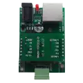
Connect the modbus gateway to PC
Due to the gateway supports various working modes, it can be wired to the computer in different ways. In TCP master mode, the gateway waits for Modbus TCP messages, then transforms it into Modbus RTU messages and forwards to the slaves connected to the gateway via RS485. By selecting RTU master mode, the gateway waits for Modbus RTU messages, then converts it into Modbus TCP messages. After that, the gateway sends the messages to the specified destination IP address. If the IP address identify an another Modbus gateway that works in TCP master mode, it interprets the messages then sends it to its slave devices. If there is a response, the other side gateway returns the response message to the gateway connected to the PC.
Connect as TCP master
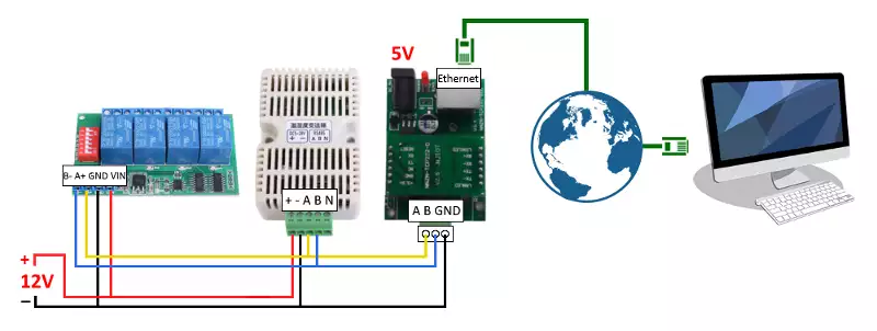
In this case, the gateway connects to the PC via Ethernet and the slaves can be connected in parallel via RS485 to the gateway, like the Figure 2 shows. When the device receive a Modbus TCP message, it will transform the message into RTU format and send it to slaves. In the figure below, you can see a 4-channel relay board and a temperature sensor as slaves. Each slave device must have a unique slave ID.
Connect as RTU master
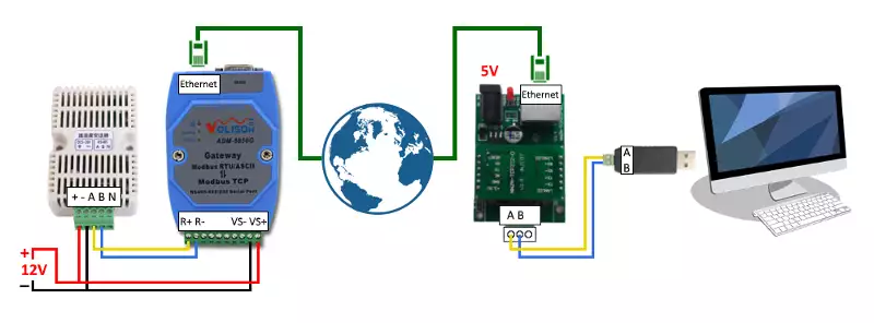
In RTU master mode, the gateway needs to be connected to the PC via USB as a slave device. To implement this, you need an USB to RS485 converter. It provides the connectivity between the PC and the standard communication port. The Figure 3 below shows how to wire them together. After you have plugged in the converter's USB to the PC, you can communicate with gateway using Modbus RTU messages. When the gateway receive the RTU message, it will transform it into TCP format and send it to the destination IP address. On the other side, there is an other Modbus RTU/TCP gateway (Volison) which operates in TCP master mode and its IP address match with the sender gateway destination IP address. This gateway transforms the received message from TCP to RTU format and send it to its slaves. The slave devices connected to the gateway must have a unique slave ID.
Specifications of Modbus gateway
| Specification | Value |
| Model | NNZN-TCP232-600pbc |
| Power supply | DC 5V |
| Working ways | TCP Master - RTU Slaver RTU Master - TCP Slaver TCP/UDP Client TCP/UDP Server |
| Baud rate | from 110bps to 115200bps |
| Ethernet interface | 10/100M |
Configure the gateway
The gateway can be configured through its user interface. To access the user interface, open your web browser then type the gateway's IP address. The default settings are shown in the Table 2 below. The PC and the modbus gateway must be in a common subnet. If it loaded, enter the password (default: 0000).
| Parameter | Default value |
| IP address | 192.168.0.7 |
| Subnet mask | 255.255.255.0 |
Configure as TCP master
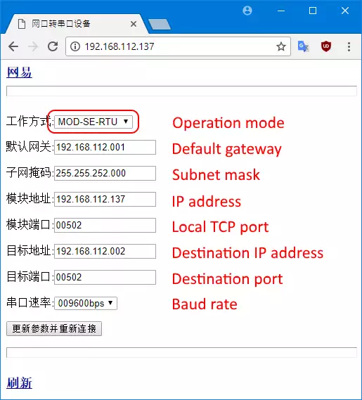
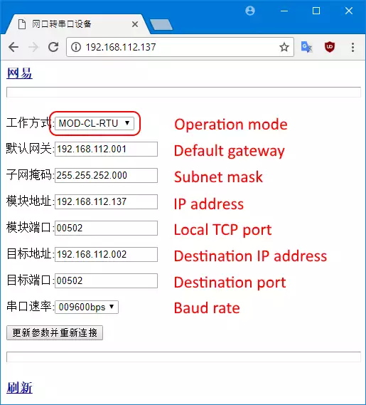
To set the working mode as TCP master, you need to select the operation mode as MOD-SE-RTU. In this case, the network is the Modbus TCP master device, and the serial port is the Modbus RTU slave device. The default gateway is the IP address of the gateway. The subnet mask and the IP address determine the accessibility of the gateway. The local TCP port is the port that you can use to connect to the device using the TCP protocol and send Modbus TCP message. The destination IP address and port are ignored in this operation mode. The baud rate must match with the baud rate of the slave devices connected to the gateway via RS485. To apply the modifications, press the button below the textboxes. The gateway will refresh the settings and will restart itself.
Configure as RTU master
To set the working mode as RTU master, you need to select the operation mode as MOD-CL-RTU. In this case, the network is the Modbus TCP slave device, the serial port is the Modbus RTU master device. The local TCP port is ignored in this operation mode. The destination IP address and port determine the accessibility of the other side modbus gateway that works in TCP master mode. So, the gateway's destination IP address and port need to be match with the other side gateway's IP address and port. Finally, the baud rate determines the baud rate of the gateway serial interface. The modbus RTU message will be delivered successfully only when it is sent to the gateway at the set baud rate. After you have set the other side gateway, click the button below the textboxes.
Examples
Let's take a 4-channel relay board as a slave device that you wish to control. This board has predetermined serial port settings (baud rate: 9600, parity: even, data bits: 8 and stop bits: 1). You need to use these settings for the communication. The examples below show, how to control the device in both TCP master and RTU master mode.
Control the relay board in TCP master mode
In this case, you need to set the operation mode as MOD-SE-RTU. Futhermore, please set the default gateway, subnet mask and IP address too. You will be able to access the modbus gateway through the specified IP address. The baud rate must be set to 9600bps due to the baud rate of the relay board is 9600. After you have applied the modifications, you can control the channels on the relay board connected to the modbus gateway via RS485 using Modbus TCP messages. There is an example what you need to send to the gateway to latch channel 1.
Control the relay board in RTU master mode
To implement the communication between the master PC and the relay board, there is a need for a Modbus RTU/TCP gateway on the sending side and another one on the receiving side. While the sending-side gateway need to work in RTU master operation mode, the receiving-side one need to operate in TCP master mode. You need to set up the receive-side gateway as explained in the example above. After that, on the sender-side, you should set the operation mode as MOD-CL-RTU. This is equals to the RTU master mode. Then, please set the IP address and port of the receiving-side modbus gateway as the destination IP address and port. Finally, set the baud rate for example to 9600bps then please save the modifications and restart the gateway. Now you can control the relay board as if it were connecting directly to the serial port of the master PC. Simply send a Modbus RTU command message to the modbus gateway to control the channels on the remote relay board.
More information
- Modbus RTU/TCP gateway (Volison)
- USB to RS485 converters
- Modbus RTU/TCP gateway (NITOT)

 Sign in