RS485 modbus connection
The ANSI EIA/TIA-485 standard, more commonly known as RS-485, specifies electrical characteristics for multi-point, balanced differential data communications systems. The Modbus® protocol is one of many that uses the RS-485 interface as its physical layer for serial data communications. Others include Profibus®, BACnet and simple ASCII.
On this page you can see how to use RS485 technology to wire Modbus Master and Slave devices. You can use 2 or 4 wires per slave, depending on half-duplex or full-duplex connection. Each slave is connected to a common GND. Do not forget to power each slave with a required voltage.
How to build a 2 wire modbus network (Half-Duplex connection)
When instruments are described as having an RS485 interface it tells you nothing for sure about the signals being transmitted. Usually just the TX and RX signals of a normal serial port are converted to RS485. The other signals of the serial port are not used. You can see that your computer can be the master device and how the USB <-> Modbus converter connects to the slaves (Figure 1). Although other master devices can be used as well.
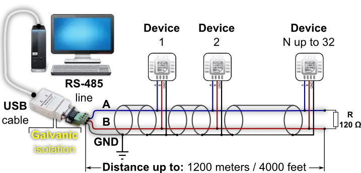
See how to create the modbus connection you saw on Figure 1 by using these slave devices. Each device should have an 'A' and 'B' wire connected. Both together forms a half-duplex communication channel. A- connects to A- and B+ connects to B+. A- and B+ together adds up to create a signal. You should connect a resistor to the end of the wires as you can see on Figure 1. Keep in mind to wire the master and slave devices to a common GND (Figure 2).
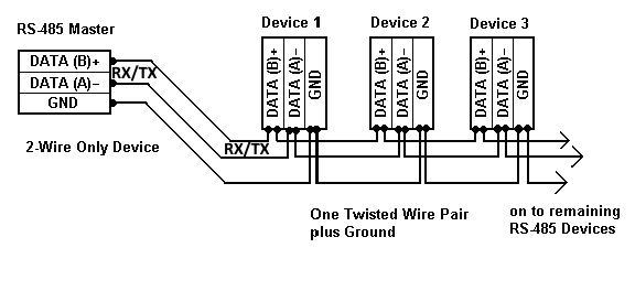
The A- and B+ wires
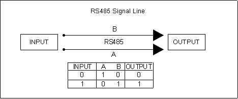
In modbus two wires are required for each signal (Figure 3). These wires are used to create a half-duplex solution (Figure 4), where the signal can travel only in one direction at once. Figure 3 shows a single RS485 signal being transmitted. Logic value 1 can be transmitted if line A is low and line B is high. Value 0 can be transmitted if line A is high and line B is low. Multiply the wires with the number of simultaneous signals. e.g. to transmit four signals, eight wires are needed
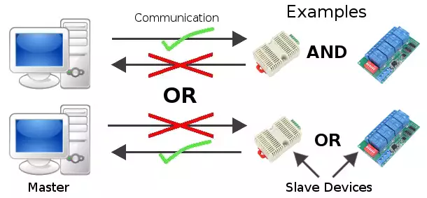
The signal travels in 1 direction at a time (Figure 4). It is not simultaneous, which makes it a half-duplex connection. This means the slaves cannot send messages while the master is speaking. Only 1 device can broadcast a signal at a time. As a contrast in full-duplex connection signals can travel in both directions simultaneously.
Wiring devices in RS485 is easy. It has a multipoint topology, where a single master is connected to multiple slaves. Here are some master devices and some slave devices. These devices are going to be compatible with Ozeki 10.
RS485 features
The advantage of the RS485 connection is that signals can be transmitted faster and over greater distance than possible with a single wire RX/TX RS232 connection (Table 1). The other adventage of RS485 is that this is not only a single connection between two devices, but a multipoint connection where a maximum of 32 slaves can be connected to the communication bus. Each slave can be addressed with it's own ID.
| Connection Type | RS232 | RS485 |
| Max Number of Slaves | 1 | 32 |
| Modes | Half/Full - Duplex | Half/Full - Duplex |
| Topology | Point-to-Point | Multipoint |
| Data Transfer Distance | 15 m | 1200 m |
| Max speed on 12 m | 20 kbs | 35 Mb |
| Max speed on 1200 m | not applicable | 100 kbs |
| Max voltage steepness | 30 V / microsec | not available |
| Resistance of the Receiver | 3 to 7 kOhm | 12 kOhm <= |
| Pilot Impedance | 3 to 7 kOhm | 54 Ohm |
| Receiver's Sensitivity | -3 to +3 V | -200 to +200 mV |
| Receiver's voltage Range | -15 to +15 V | -7 to +12 V |
| Output's max voltage | -25 to +25 V | -7 to +12 V |
| Output's min voltage | -5 to +5 V | -1.5 to +1.5 V |
You can connect 247 slave devices to a master device by using multiple half-duplex repeaters. The slaves can be addressed by 247 different ID-s. Although without a repeater, only 32 different devices can be used.
How to build a 4 wire modbus network (Full-Duplex connection)
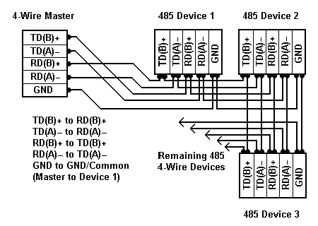
Full Duplex means that data can pass simultaneously both directions. This requires 4 wires - one pair to Transmit and one pair to Receive (Figure 5). The computer alone controls the TX transmit line. It sends out a message which includes an Address. The addressed instrument alone replies by driving the RX line of the PC. The advantage of the 4-wire connection is that all devices only see commands from the Master, and no Device sees the responses from other devices. Instead of your PC you can find other master devices supporting 4 wires. Keep in mind that the RX of the master must be connected to the TX of the slave and vice versa. A B+ can be only connected to B+ and A- to A- as seen on Table 2.
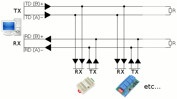
This connection is used for a single Master in a 4-wire system (Figure 6). When only one master is used, the Master can be set to RS-422 mode since there is no need to share the transmit wire pair to the Receivers of all the devices. All of the devices must be RS-485 and Tri-state since the same wire pair to the Receiver must be shared by the Transmitters of all the devices. See how the devices should be connected to eachother (Table 2).
| Master | Device 1 | Device 2 |
| TD A+ | RD A+ | RD A+ |
| TD B+ | RD B+ | RD B+ |
| RD A+ | TD A+ | TD A+ |
| RD B+ | TD B+ | TD B+ |
Preventing Voltage Reflection
When a signal is sent down a cable there is always a reflection voltage which returns up the cable. This reflection is bigger as signals' edges get faster and lines get longer. It can be minimised by terminating the ends of the line with the characteristic impedance of the system. This is 120 ohm for RS485.
Ideal RS485 Wiring
Ideally an RS485 system consists of a single linear cable (no branches) with 120 ohm resistors connected across the 2 wires at each end of the cable. RS485 can handle speeds of over 10 Mbits per second and line lengths of over 1 km. If you are operating anywhere near these values you must arrange your wiring close to the ideal. For many applications where baud rates are slow (say 9600 baud), and lines are only tens of meters long, this is not essential.
Contents retrieved from
- http://www.bb-elec.com/
- http://www.windmill.co.uk/
More information
- RS485 modbus connection
- Control modbus with TCP protocol
- Control modbus with UDP protocol
