How to connect multiple devices to the SPI bus
After reading the tutorial below, you will be fully familiar with connecting multiple devices to the SPI bus. Serial Peripheral Interface (SPI) is an interface bus commonly used to send data between microcontrollers and small peripherals such as shift registers, sensors, and SD cards. It uses separate clock and data lines, along with a select line to choose the device you wish to talk to.
Contents
- Receiving Data
- Slave Select (SS)
- Connecting multiple slaves
- Programming for SPI
- Pros and Cons for using SPI
- References
Receiving Data
One-way communications may sounds great, but how do you send data back in the opposite direction? Let's see it.
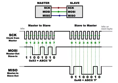
In SPI, only one side generates the clock signal (usually called CLK or SCK for Serial ClocK). The side that generates the clock is called the master, and the other side is called the slave. There is always only one master (which is almost always your microcontroller), but there can be multiple slaves (more on this in a bit).
When data is sent from the master to a slave, it's sent on a data line called MOSI, for Master Out / Slave In. If the slave needs to send a response back to the master, the master will continue to generate a prearranged number of clock cycles, and the slave will put the data onto a third data line called MISO, for Master In / Slave Out.

'Prearranged' refers to that the master always generates the clock signal, it must know in advance when a slave needs to return data and how much data will be returned. This is very different than asynchronous serial, where random amounts of data can be sent in either direction at any time. In practice this is not a problem, as SPI is generally used to talk to sensors that have a very specific command structure. For example, if you send the command for “read data” to a device, you know that the device will always send you, for example, two bytes in return. (In cases where you might want to return a variable amount of data, you could always return one or two bytes specifying the length of the data and then have the master retrieve the full amount.)
SPI is 'full duplex' (has separate send and receive lines), and in certain situations, you can transmit and receive data at the same time (e.g. requesting a new sensor reading while retrieving the data from the previous one). The datasheet of our device shows if this is possible.
Slave Select (SS)
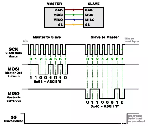
SS (Slave Select) line tells the slave that it should wake up and receive / send data and is also used when multiple slaves are present to select the one you would like to talk to.

The SS line is normally held high, which disconnects the slave from the SPI bus. (This type of logic is known as active low, and you will often see used it for enable and reset lines.) Just before data is sent to the slave, the line is brought low, which activates the slave. When you are done using the slave, the line is made high again. In a shift register, this corresponds to the latch input, which transfers the received data to the output lines.
Connecting multiple slaves
There are two ways of connecting multiple slaves to an SPI bus:
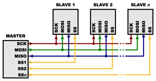
Option 1: Each slave will need a separate SS line
In general, each slave will need a separate SS line. To talk to a particular slave, you will make that slave’s SS line low and keep the rest of them high (you do not want two slaves activated at the same time, or they may both try to talk on the same MISO line resulting in garbled data). Lots of slaves will require lots of SS lines; if you’re running low on outputs, there are binary decoder chips that can multiply your SS outputs.

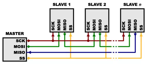
Option 2: A single SS line goes to all the slaves
On the other hand, some parts prefer to be daisy-chained together, with the MISO (output) of one going to the MOSI (input) of the next. In this case, a single SS line goes to all the slaves. Once all the data is sent, the SS line is raised, which causes all the chips to be activated simultaneously. This is often used for daisy-chained shift registers and addressable LED drivers.

For this layout, data overflows from one slave to the next, so to send data to any one slave, you will need to transmit enough data to reach all of them. Also, keep in mind that the first piece of data you transmit will end up in the last slave.
This type of layout is typically used in output-only situations, such as driving LEDs where you do not need to receive any data back. In these cases you can leave the master’s MISO line disconnected. However, if data does need to be returned to the master, you can do this by closing the daisy-chain loop (blue wire in the above diagram). Note that if you do this, the return data from slave 1 will need to pass through all the slaves before getting back to the master, so be sure to send enough receive commands to get the data you need.
Programming for SPI
Many microcontrollers have built-in SPI peripherals that handle all the details of sending and receiving data, and can do so at very high speeds. The SPI protocol is also simple enough that you can write your own routines to manipulate the I/O lines in the proper sequence to transfer data.
uint8_t SPI_transfer_byte(uint8_t byte_out)
{
    uint8_t byte_in;
    uint8_t bit;

    for (bit = 0; bit < 8; bit++) {

       /* Shift-out a bit to the MOSI line. */
       if (byte_out & 0x80)
           write_MOSI(HIGH);
       else
           write_MOSI(LOW);
       byte_out <<= 1;

       /* Delay for at least the peer's setup time. */
       delay(SPI_SCLK_LOW_TIME);

       /* Pull the clock line high. */
       write_SCLK(HIGH);

       /* Shift-in a bit from the MISO line. */
       byte_in <<= 1;
       if (read_MISO() == HIGH)
           byte_in |= 1;

       /* Delay for at least the peer's hold time. */
       delay(SPI_SCLK_HIGH_TIME);

       /* Pull the clock line low. */
       write_SCLK(LOW);
   }

   return byte_in;
}
If you’re using an Arduino, there are two ways you can communicate with SPI devices:
- You can use the shiftIn() and shiftOut() commands. These are software-based commands that will work on any group of pins, but will be somewhat slow.
- Or you can use the SPI Library, which takes advantage of the SPI hardware built into the microcontroller. This is vastly faster than the above commands, but it will only work on certain pins.
You will need to select some options when setting up your interface. These options must match those of the device you’re talking to; check the device’s datasheet to see what it requires.
- The interface can send data with the most-significant bit (MSB) first, or least-significant bit (LSB) first. In the Arduino SPI library, this is controlled by the setBitOrder() function.
- The slave will read the data on either the rising edge or the falling edge of the clock pulse. Additionally, the clock can be considered idle when it is high or low. In the Arduino SPI library, both of these options are controlled by the setDataMode() function.
- SPI can operate at extremely high speeds (millions of bytes per second), which may be too fast for some devices. To accommodate such devices, you can adjust the data rate. In the Arduino SPI library, the speed is set by the setClockDivider() function, which divides the master clock (16MHz on most Arduinos) down to a frequency between 8MHz (/2) and 125kHz (/128).
- If you are using the SPI Library, you must use the provided SCK, MOSI and MISO pins, as the hardware is hardwired to those pins. There is also a dedicated SS pin that you can use (which must, at least, be set to an output in order for the SPI hardware to function), but note that you can use any other available output pin(s) for SS to your slave device(s) as well.
- On older Arduinos, you will need to control the SS pin(s) yourself, making one of them low before your data transfer and high afterward. Newer Arduinos such as the Due can control each SS pin automatically as part of the data transfer.
Pros and Cons for using SPI
Advantages of SPI
- It is faster than asynchronous serial
- The receive hardware can be a simple shift register
- It supports multiple slaves
Disadvantages of SPI
- It requires more signal lines (wires) than other communications methods
- The communications must be well-defined in advance (you can not send random amounts of data whenever you want)
- The master must control all communications (slaves can not talk directly to each other)
- It usually requires separate SS lines to each slave, which can be problematic if numerous slaves are needed.
References
- https://learn.sparkfun.com/tutorials/serial-peripheral-interface-spi/all
- shiftIn() : http://arduino.cc/en/Reference/ShiftIn
- shiftOut() : http://arduino.cc/en/Reference/ShiftOut
- SPI library : http://arduino.cc/en/Reference/SPI
- setBitOrder() : http://arduino.cc/en/Reference/SPISetBitOrder
- setDataMode() : http://arduino.cc/en/Reference/SPISetDataMode
- setClockDivider() : http://arduino.cc/en/Reference/SPISetClockDivider
