Digital counter
This is an electronic unit with four digital counter imputs. It has a Modbus RTU communication interface to provide a simple way for integrating digital signals to supervisory system. The input signals are isolated from the power thus protecting the electrical instruments by eliminating ground loop effects. This guide shows you how to set up and how to communicate with the device.

Connect the digital counter to PC
Note: the RS485 to USB converter mentioned below does not support 'even' parity which is the default setting for the device. Before you try to communicate with it, please read the chapter of setting up the digital counter.
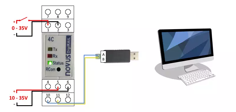
This unit is a Novus DigiRail-4C device. It has four digital input (1, 3, 7 and 9 terminals). On the Figure 1 below, you can see how to wire the first one. In case of inputs, the voltage range can be between 0 and 35 voltages, but the logical level 0 is in the range of 0 and 1 volts, while the logical level 1 is between 4 and 35 voltages. The digital counter module operates between 10 and 35 volts. So you need to connect the power supply to terminal 5 for positive and 6 for negative. Finally, the last three terminals are the serial port connectors that stands for the Modbus connection. To communicate with the module, you need an RS485 to USB converter. It provides the connectivity between the PC and the serial port of the device. The complete instruction manual available here.

Specifications of the digital counter
The inputs are electrically insulated from the serial interface and the module supply. There is no electrical insulation between serial interface and unit supply as well as between the common negative terminals (terminal 2 and 8). The maximum count frequency is 1000 Hz for signals with square wave and working cycle of 50%, but the input 1 can be configured for counting signals of up to 100 kHz. The unit capable of counting pulses in given time intervals and retaining peak counting in given time intervals. The time intervals are independent for both functions. All the important parameters are summarized in the following Table 1.
| Specification | Value |
| Power supply | 10 - 35V DC / 50 mA max |
| Counting capacity | 32 bits (0 to 4.294.967.295) |
| Input number | 4 digital inputs |
| Input levels |
logical level 0: 0 to 1V DC logical level 1: 4 to 35V DC |
About Modbus
Modbus is a serial communication protocol that uses command and response frames to implement the communication between one master and many slaves. Only one master is connected to the bus, and one or several (247 maximum) slaves are also connected to the same serial bus. The Modbus communication is always initiated by the master. There are several versions of Modbus protocol that you can find more information about under Connections. The master can write the register values of the slave device and get them by sending a command message. The slave device sends back a response one that contains the requested information.
Setting up the digital counter
To communicate with the unit, you need to know its serial port parameters. The
Table 2 below shows the possible ones as well as the factory default and
the set values in diagnostics mode. If you have a new one, you need to use the
factory default. If it has been already used and you do not know its
communication parameters, please press the RCom button on the front panel of the
device to enter diagnostics mode for 1 minute.
In both case, the parity mode of the unit is 'even'. Many RS485 to USB
converters does not support this mode. So you need a special converter
like this one
to communicate with the device successfully. Then you can set the parity to
'none'. After you have changed it, you can communicate with it using a simple
converter like the mentioned one on the wiring diagram above. There is an
example below how to set the parity to none.
| Link | Possible values | Factory default | Diagnostics mode |
| Baud rate (bit/s) | 1200 - 115200 | 1200 | 1200 |
| Parity | none / odd / even | even | even |
| Stop bit | 1 | 1 | 1 |
| Slave ID | 1 - 247 | 247 | 246 |
| Data bits | 8 | 8 | 8 |
Connect more digital counter
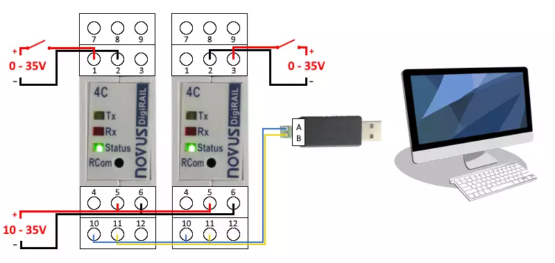
You can connect more digital counter to the same line like the Figure 2 shows. For successful communication, the serial port parameters of the device must be match with each other and every device must be have a unique slave ID to distinguish them. Maximum 247 devices can be connected to the same line due to Modbus protocol.

Modbus frame of digital counter
The digital counter supports modbus function code 4 and 6. By using function code 4, you can read data from the device such as current states of digital inputs or counted pulses on each input. By using function code 6, you can write values to the device, for example you can set the serial port parameters, the slave ID or tags for the device and inputs. In both case, the Modbus RTU command frame build up from 8 bytes totally. It is constructed from 1 bytes address field that contains the unique slave ID. Then, there is 1 byte function code field. In this case, it can be 0x04 for reading and 0x06 for writing values. It is followed by 4 bytes data field. For function code 4, this contains information about what to read. For function code 6, it contains the data about the register address and the value to set. Finally, there is 2 bytes checksum field calculated from the previous 6 bytes using CRC-16.
| Address | Function | Data | Checksum |
Read state of digital input 1
The first byte determines the slave ID of the device. This value can be between 1 and 247 (0x00 - 0xF7). For reading, the function code 3 (0x03) should be used. This identifies the reading of 40000's registers. The register offset specify the exact address of the register. To determine register #40008 that contains the digital input 1 state, the offset should be 8 (0x0008). The register length tells how many registers need to be read from the specified one. It is currently 1 (0x0001), because the states stored in one register. The last 2 bytes are the checksum calculated from the previous 6 bytes. The following Table 4 shows the command frame to read the state of digital input 1.
| Slave ID | Function | Register offset | Register length | CRC-16 | |||
| 01 - F7 | 03 | 00 | 08 | 00 | 01 | 2 bytes CRC | |
There is an example below what you need to send exactly if the slave ID is 247. After you have sent the message, the device will send back a response message and its data field will contain the current digital input 1 state.
Set parity
The first byte is the slave ID again. For writing 40000's registers, the function code 6 (0x06) needs to be used. This identifies the writing of single 4X registers. The module stores the value of parity setting in its holding register #40004. So, the register offset should be 4 (0x04). In this case the value field can be between 0 and 2 (0x0000 - 0x0004). The value 0x0000 equals to parity none, 0x0001 equals to odd and 0x0002 equals to even. Finally, there is 2 bytes checksum field. The Table 5 below shows the command frame to set the parity of the device.
| Slave ID | Function | Register offset | Value to set | CRC-16 | |||
| 01 - F7 | 06 | 00 | 04 | 00 | 00 - 02 | 2 bytes CRC | |
After you have sent a command message, you will receive a response one containing the modification information. Once you have received the response message, the digital counter will be accessed using the set parity. The example found below shows how to set the parity to none if the slave ID of the device is 247.
The digital counter also supports many other functions like setting tags, reading counted pulses in last interval for each input etc. You can read more about it using the communication manual of the digital counter.
Examples
Read state of digital input 1
The following qwerty reads the state of digital input 1 if the slave ID of the module is 247.
| Octet(s) | Description | Format | In this example |
| F7 | slave ID | hex-octet | slave ID of the digital counter is 247 |
| 03 | function code | hex-octet | function code 3 reads the contents of holding (4X) registers |
| 00 08 | register offset | hex-octet | determines the register #40008 containing the state of input 1 |
| 00 01 | register length | hex-octet | value of input state stored in one register |
| 11 5E | checksum | hex-octet | checksum calculated from the previous 6 bytes using CRC-16 |
The response message below returns the state of digital input 1 as off.
| Octet(s) | Description | Format | In this example |
| F7 | slave ID | hex-octet | slave ID of the digital counter is 247 |
| 03 | response code | hex-octet | equals to the function code sent in command message |
| 02 | data length | hex-octet | data bytes will be 2 bytes long |
| 00 00 | data | hex-octet | 0 equals to off described in the manual of the device |
| 70 51 | checksum | hex-octet | checksum calculated from the previous 5 bytes using CRC-16 |
Read value of digital input 1 counts
This one reads the value of the input 1 if the slave ID of the module is 247. It is similar to the previous example above with the difference that the value of the digital input 1 counts is stored not in 1, but in 2 adjacent registers.
| Octet(s) | Description | Format | In this example |
| F7 | slave ID | hex-octet | slave ID of the digital counter is 247 |
| 03 | function code | hex-octet | function code 3 reads the contents of holding (4X) registers |
| 00 12 | register offset | hex-octet | determines the register #40018 containing the value of input 1 counts |
| 00 02 | register length | hex-octet | value of input 1 counts stored in two register |
| 70 98 | checksum | hex-octet | checksum calculated from the previous 6 bytes using CRC-16 |
The response message below returns the value of the input 1 counts as 19.
| Octet(s) | Description | Format | In this example |
| F7 | slave ID | hex-octet | the slave ID of the digital counter is 247 |
| 03 | response code | hex-octet | equals to the function code sent in command message |
| 00 04 | data length | hex-octet | data bytes will be 4 bytes long |
|
00 00 00 13 |
data | hex-octet | value of the digital input 1 counts is equal to 19 |
| 8D A4 | checksum | hex-octet | checksum calculated from the previous 8 bytes using CRC-16 |
Set parity to none
The following qwerty sets the parity of the device to none if the module's slave ID is 247.
| Octet(s) | Description | Format | In this example |
| F7 | slave ID | hex-octet | slave ID of the digital counter is 247 |
| 06 | function code | hex-octet | function code 6 writes the contents of the holding (4X) register |
| 00 04 | register offset | hex-octet | determines the register #40004 containing the parity value of the device |
| 00 00 | value | hex-octet | 0 equals to parity 'none' described in the manual of the unit |
| DC 9D | checksum | hex-octet | checksum calculated from the previous 6 bytes using CRC-16 |
The response message below returns that the parity setting above has been successful.
| Octet(s) | Description | Format | In this example |
| F7 | slave ID | hex-octet | slave ID of the digital counter is 247 |
| 06 | response code | hex-octet | equals to the function code sent in command message |
| 00 04 | register offset | hex-octet | modified register, equals to command message's one |
| 00 00 | register value | hex-octet |
if it equals to the 'value' bytes sent in command message, the operation has been successful |
| DC 9D | checksum | hex-octet | checksum calculated from the previous 6 bytes using CRC-16 |
