Control modbus with TCP protocol
The Transmission Control Protocol (TCP) is one of the main protocols of the Internet protocol suite. TCP is used extensively by many applications available by internet, including www, E-mail, File Transfer Protocol, Secure Shell, peer-to-peer file sharing, and streaming media applications.
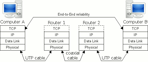
You can see a simple TCP diagram showing a www application where two computers communicate on the internet. This diagram contains the most common types of physical communication (Figure 1), but the Wi-Fi technology is also a widely accepted communication form between the router and the PC.
The TCP (Transmission Control Protocol) is an important network protocol that is used in the transmission of data over networks. A protocol is a set of rules and procedures that govern how the transmission of data is carried out so that everyone, independently of the location, software or hardware used, does the thing the same way.
- IP: The Internet Protocol (IP) is the principal communications protocol in the Internet protocol suite for relaying datagrams across network boundaries. Its routing function enables internetworking, and essentially establishes the Internet. The Internet protocol suite is therefore often referred to as TCP/IP.
- Data Link: The data link layer is the second layer of the seven-layer OSI model of computer networking. The data link layer provides the functional and procedural means to transfer data between network entities and might provide the means to detect and possibly correct errors that may occur in the physical layer.
- Physical: The physical layer consists of the electronic circuit transmission technologies of a network. It is a fundamental layer underlying the higher level functions in a network. Due to the plethora of available hardware technologies with widely varying characteristics, this is perhaps the most complex layer in the OSI architecture.
Each physical layer is connected to the other with some kind of transfer method like UTP cable or Wi-Fi. The physical layer is also considered the domain of many hardware-related network design issues, such as LAN and WAN topology. In table 1 you can read about all 7 layers of the OSI model.
| OSI Layers | Protocol data unit (PDU) | Function |
| Application | Data | High-level APIs, including resource sharing, remote file access |
| Presentation | Data | Translation of data between a networking service and an application including character encoding, data compression and encryption/decryption |
| Session | Data | Managing communication sessions i.e. continuous exchange of information in the form of multiple back-and-forth transmissions between two nodes |
| Transport (TCP, UDP) | Segment (TCP) / Datagram (UDP) | Reliable transmission of data segments between points on a network including segmentation, acknowledgement and multiplexing |
| Network (IP) | Packet | Structuring and managing a multi-node network including addressing, routing and traffic control |
| Data Link | Frame | Reliable transmission of data frames between two nodes connected by a physical layer |
| Physical | Bit | Transmission and reception of raw bit streams over a physical medium |
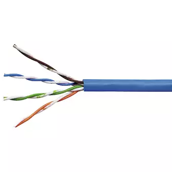
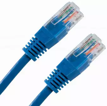
Unshielded twisted pair (UTP) are mostly used in the physical layer. A typical subset of these colors (white/blue, blue/white, white/orange, orange/white) shows up in most UTP cables (Figure 2-3). The cables are typically made with copper wires measured at 22 or 24 American Wire Gauge (AWG), with the colored insulation typically made from an insulator such as polyethylene or FEP and the total package covered in a polyethylene jacket.
UTP uses twisted wire pairs. Twisted pair cabling is a type of wiring in which two conductors of a single circuit are twisted together for the purposes of improving electromagnetic compatibility. Twisted pair cabling is often used in data networks for short and medium length connections because of its relatively lower costs compared to optical fiber and coaxial cable.
|
|
|
Wi-Fi is another physical layer type. It works on the basis of IEEE 802.11 Standard. The protocol architecture consists of Physical Layer with two sublayers PLCP & PMD and Data Link Layer consists of MAC and LLC sublayer. The Wi-Fi network consist of a Wi-Fi client, access point and LAN. LAN may consist of Ethernet Switch, RADIUS Authentication Server etc.
Basically Wi-Fi works in half-duplex mode and Wi-Fi standard consist of only Physical Layer and Data Link Layer. Other layers are similar to TCP/IP model or OSI model in other applications.
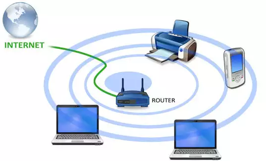
The physical layer can transfer both TCP or UDP packages, although this page describes TCP only, so let's continue by examining the TCP link between two stations (e.g. computer). You will also see how a TCP package header looks like and how a TCP package is sent between stations.
TCP adds a great deal of functionality to the IP service

- Streams: TCP data is organized as a stream of bytes, much like a file. The datagram nature of the network is concealed. A mechanism (the Urgent Pointer) exists to let out-of-band data be specially flagged.
- Reliable delivery: Sequence numbers are used to coordinate which data has been transmitted and received. TCP will arrange for retransmission if it determines that data has been lost.
- Network adaptation: TCP will dynamically learn the delay characteristics of a network and adjust its operation to maximize throughput without overloading the network.
- Flow control: TCP manages data buffers, and coordinates traffic so its buffers will never overflow. Fast senders will be stopped periodically to keep up with slower receivers. Above you can see the flow control diagram (Figure 5).
Full-Duplex Operation
No matter what the particular application, TCP almost always operates full-duplex (Figure 6). It's sometimes useful to think of a TCP session as two independent byte streams, traveling in opposite directions. No TCP mechanism exists to associate data in the forward and reverse byte streams. Only during connection start and close sequences can TCP exhibit asymmetric behavior (i.e. data transfer in the forward direction but not in the reverse, or vice versa).

TCP header
It is larger than an UDP header but uses the same port assignment scheme as UDP does. Unlike UDP, a 32-bit sequence number and acknowledgment number are included in the header as well as several flag bits. Only a few of the flag bits will be discussed here. Since the TCP header can be of varying length depending upon the content of the options field, a data offset field has been provided in order to determine the actual beginning of the data. The padding field has been provided so that the options field along with the padding field will end on a 32-bit boundary. This is typically done with all the headers within the TCP/IP stack. A window field in the header indicates to the sender how much data the receiver is willing to accept. This feature is used for flow control, which attempts to prevent buffer overflow in the receiver. Finally, data follows the TCP header. The header can be up to 40 bytes in length and the header with its appended data is called a segment. A checksum field ensures the integrity of the header and its associated data (Figure 7).
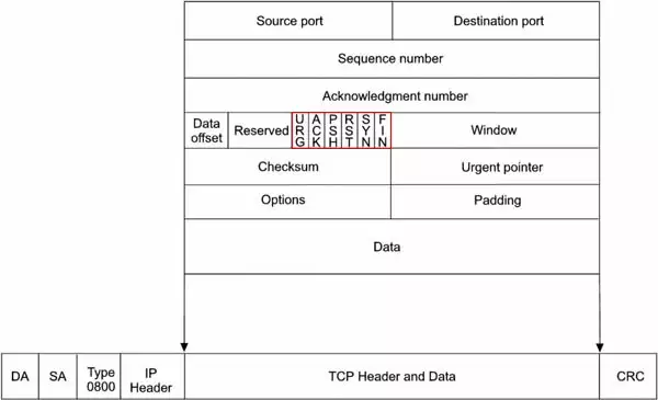
The TCP header contains several one-bit boolean fields known as flags to influence the dataflow:
- URG - A segment is urgent and should be prioritized
- ACK - Acknowledges received data
- PSH - Informs the receiving host that the data should be pushed up to the receiving application
- RST - Aborts a connection in response to an error
- SYN - Initiates a connection
- FIN - Closes a connection
Using Connections
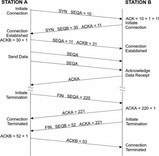
When using the TCP protocol with processes, a connection must be first established and maintained in order to provide for the flow of data. By establishing a connection between two stations (Figure 8), the proper buffer area is provided for the impending data. When station A wants to communicate to station B, it must first establish a connection which allows for the synchronization of sequence numbers and acknowledgments. One of the flags within the TCP header is the SYN bit, which is used to indicate the initial sequence number when a connection is established. This informs the receiver to synchronize its error checking means to this sequence number. Therefore, station A sends a TCP segment with SYN set and its sequence number, which in this case is 10, to station B. Station B responds by sending an acknowledgment with the value 11 to indicate that is the value of the sequence number it expects to receive next. Station B has its own sequence number that it sends to station A. In this case it is 30 which station A acknowledges by sending out a 31. This establishes two connections. Once the connections are established, data is sent from station A to station B with station A incrementing sequence numbers and station B acknowledging them. This is what is called a full-duplex connection since two connections were established; one from A to B and another from B to A.
Once the required data transfer has been completed, the two connections should be terminated in order to free up buffer space in the two stations. There is a flag called FIN, which is used to terminate the connection. Station A sends a TCP segment with FIN flag sent along with a sequence number. Station B acknowledges the request and once the acknowledgment is received at Station A, the connection from A to B is terminated. This does not mean that the connection from B to A is terminated. This must be done in a like fashion in order to terminate the full-duplex connection.
Flow Control
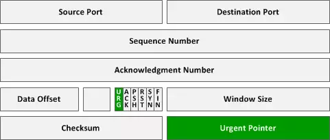
It is the management of data transfer between two stations. Depending upon the role of the station, be it client or server, or its processing power, a station may not be able to keep up with the network traffic. In order to slow down events, the TCP header has a field called window. The receiving station sets a value in the window field informing the sender how many bytes of data it will accept. The window is dynamic and the window can be increased as buffer space in the receiver becomes available. The window can also be zero halting transmission. If the sender still needs to communicate important information while in this condition, it can send out a segment with the URG (urgent) flag set along with a sequence number (Figure 9) in the urgent pointer field that indicates the first byte of data following the urgent data. The receiver should always allow room for urgent data.
Summary
If the goal is secure and reliable communication, TCP is the best choice. Both TCP and UDP application protocols use port numbers (find all ports here) and when used with IP addresses create unique socket definitions across the network. These socket definitions facilitate the processes between the stations on the control network.
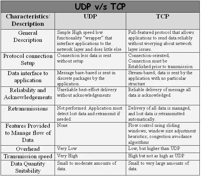
As a summary read about the most significant differences of the two IP protocols (Figure 10). TCP is more reliable although slower. UDP is faster, but less reliable, since there is no data acknowledgement in UDP and it has no connection setup handshake, while TCP has. This guarantees the speed of the UDP. Thanks to data acknowledgement TCP repeats false messages. This means it can transfer large amount of data reliably.
You can use Modbus devices through any TCP connection with the Modbus TCP/IP protocol. Modbus TCP/IP was born by combining a versatile, scaleable, and ubiquitous physical network (Ethernet) with a universal networking standard (TCP/IP) and by integrating Modbus packages in the data field of the TCP/IP protocol. This gives a truly open, accessible network for exchange of process data. It is simple to implement for any device that supports TCP/IP sockets.
Contents retrieved from
- https://networking.ringofsaturn.com/Protocols/tcp.php
- http://www.industrialethernetu.com

