Smart Alarm system
Create a high quality, smart and very effective alarm system controlled by your Ozeki 10 server.
Please install it and connect all available security sensors to Ozeki.
Just think about how many cameras and smoke detectors are placed all over the building.
I can tell you that you can easily connect all RTSP and USB cameras, radio frequency and wired infrared motion sensors to
this software.
Most IR (infrared) sensors can easily send signals through the 433 MHz radio frequency.
Additionally you can also wire any analog sensor directly to Ozeki 10.
All of these can make it the best smart building and robot operating system ever created.
The next easy step is to configure Ozeki 10 to quickly forward all alarm events to every eligible person.
It is a good decision to alarm the owner or janitor to check on the asset with SMS, automated phone calls or e-mails.
Do not forget, you have unlimited possibilities to reach out for help.
Ozeki 10 can prevent fire disasters or burglaries.
Detect motion or human faces. In this case all video files can be automatically forwarded
in real time to the police, so they can react in time. The video records are your evidence.
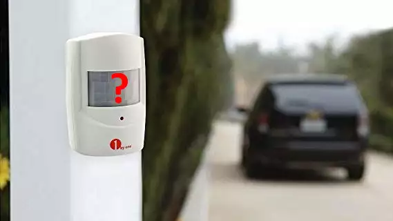
STEP 1: Do you have infra motion detectors
Check if you have a motion detector inside or outside, then find out if it communicates wirelessly on 315 or 433 MHz frequency. Smoke sensors are also accepted, as a matter of fact all alarm sensors that send 315 or 433 MHz signals can be automatically detected with the antenna that forwards the message through a microcontroller to your Ozeki 10. Most sensors only transmit, but if you can also receive commands to your sensor then you can use Ozeki to control them or set sensor options. If you do not have one, buy a wireless PIR sensor or smoke alarm for this guide to have some great experience and build it in your home if you like it. You will feel more comfort if your house is safe from fire and protected from burglary.
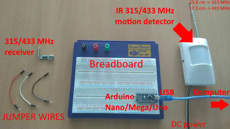
STEP 2: Get the parts
If your alarm system cannot receive signals, you will not need a transmitter, but acquiring a 433 or 315 MHz receiver is high priority for this guide:- A wireless motion detector (or smoke alarm)
- Raspberry Pi 2/3 (or Asus Tinker Board)
- Arduino Nano, Uno or Mega
- RF 315 or 433 MHz receiver (transmitter is optional)
- breadboard (to build your first RF circuit on)
- Jumper wires and a single USB cable
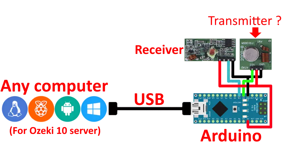
STEP 3: Easy to build circuit diagram
This is an easy to build RF transceiver circuit, which you can connect to your Ozeki 10 computer through a mini USB cable. Make sure that the cable is compatible with your Arduino. The Mega and Nano use different USB sockets. Be careful when connecting the red and black wires to the RF modules, because reverse voltage can ruin both the module and Arduino. The circuit will only work with a properly installed Arduino code and Ozeki 10 server. You will be lead through this guide how to make the installations.
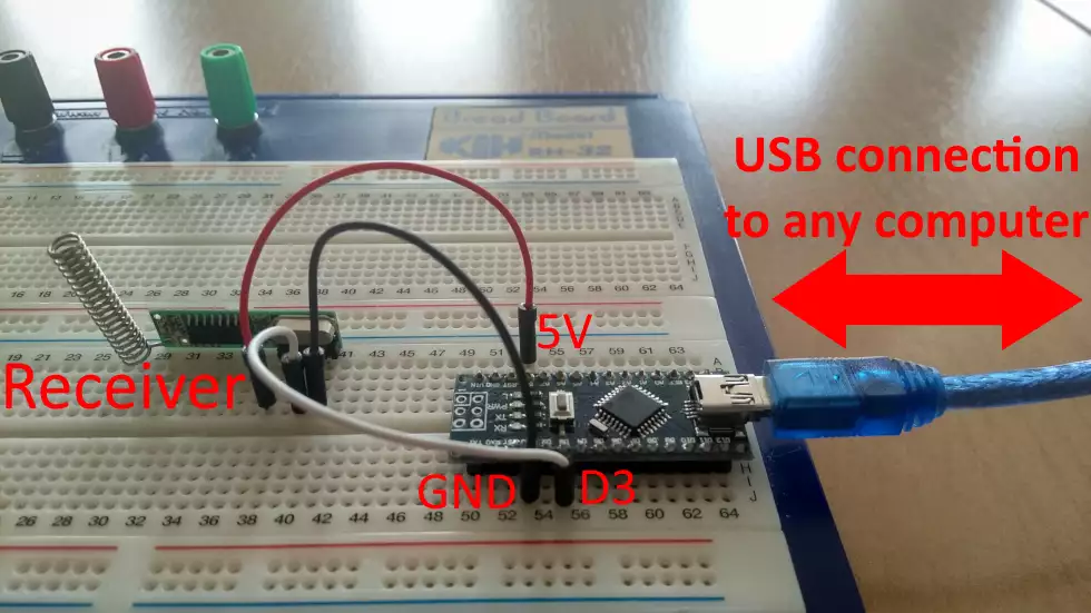
STEP 4: Test it on a board
This is how the circuit is wired on a test panel. Even for professionals, a test panel is highly suggested before creating a printed circuit board. If you look at the picture below, you can see that the transmitter is deliberately left out. This is because this is an easier construction handling incoming signals. Unfortunately the D3 receiver pin cannot be modified, please connect it as you see it on the picture below. The only reason for this is that the D3 is the interrupt pin (INT1). It detects rising and falling edges from the receiver.
STEP 5: Download and install Ozeki to your computer
Ok, so back to the computer, please make sure that Ozeki 10 is installed properly on the operating system you use. Select the installer to download it from http://www.ozeki.hu/index.php?owpn=231 If you have problem with the installation, you can find installation tutorials in the Ozeki 10 guide at http://www.ozeki.hu/index.php?owpn=5980 This is a good idea to start with.
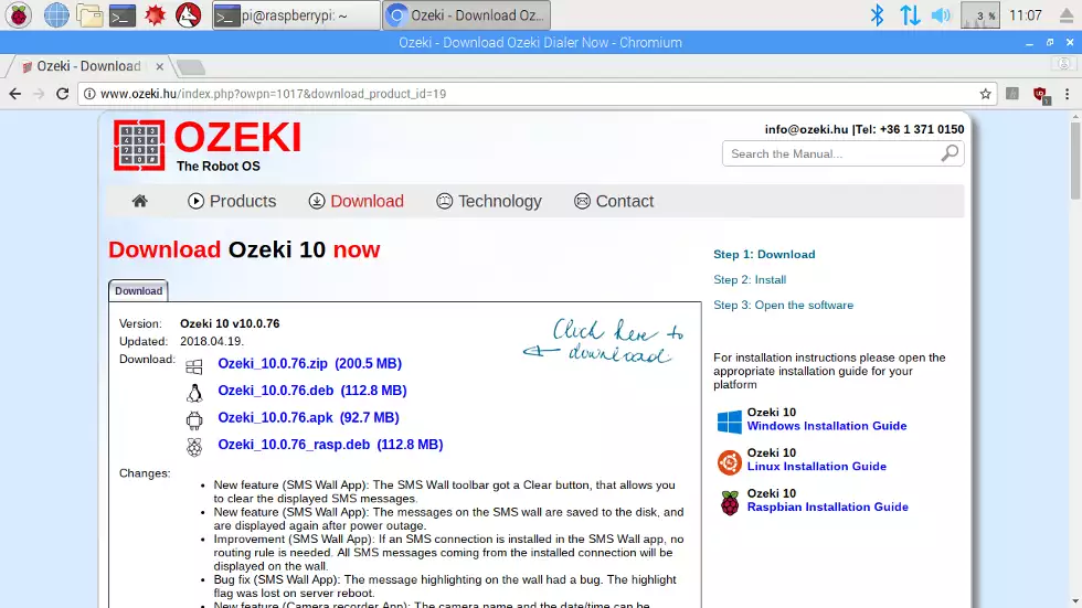
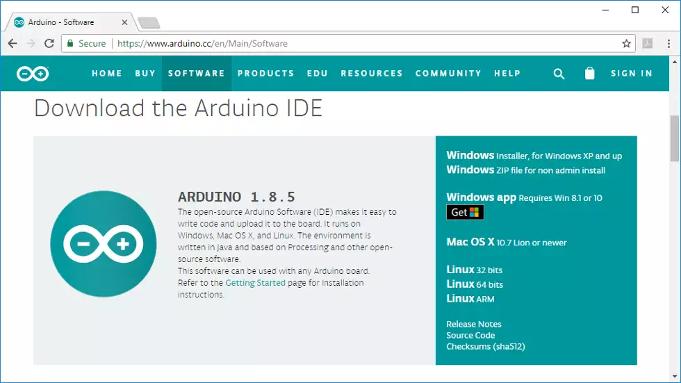
STEP 6: Install Arduino IDE if you do not have it
The https://www.arduino.cc is the official Arduino website supporting programming interfaces for multiple OS -s. It depends which OS you would like to use to upload the Arduino codes. It is suggested to use the same OS you have installed Ozeki 10 on, because the Ozeki 10 Arduino libraries are on the same machine. If using different computer, copy the libraries to it too.
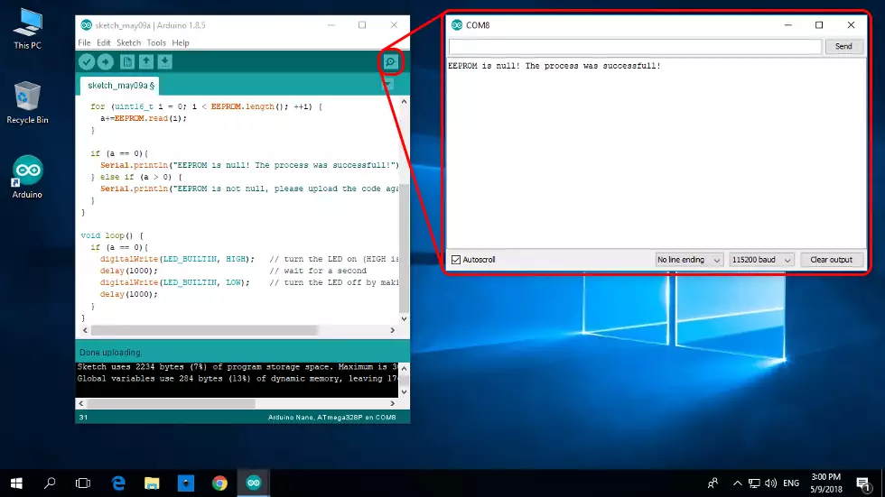
STEP 7: Clear the Arduino EEPROM
The EEPROM contains all Arduino device ID -s, so please wipe it with the following code http://www.ozeki.hu/index.php?owpn=3110. After copy pasting and installing the code, please open serial communication and read the message to read if the the EEPROM has been successfully cleared. Keep in mind that all new code uploads require an empty COM port. If the port is occupied, it is because another software is using it too, so free it up.
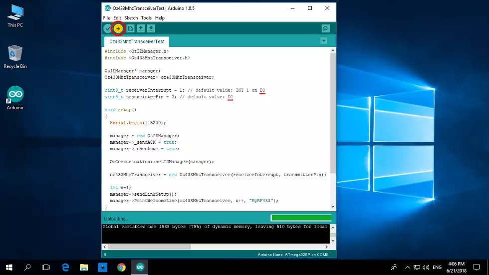
STEP 8: Upload Arduino RF code
http://www.ozeki.hu/attachments/5971/RF_transceiver_code.txt (copy)
Uploading the code above is really important to transfer microcontroller codes from the receiver module to the Ozeki 10 machine. The code supports
transmitter the RF module too, so if you have connected it, you will have no problem using it. The code is capable to
control both 315 or 433 MHz receiver and transmitter modules. If successful, start Ozeki 10.
STEP 9: Start Control Panel. It detects your device
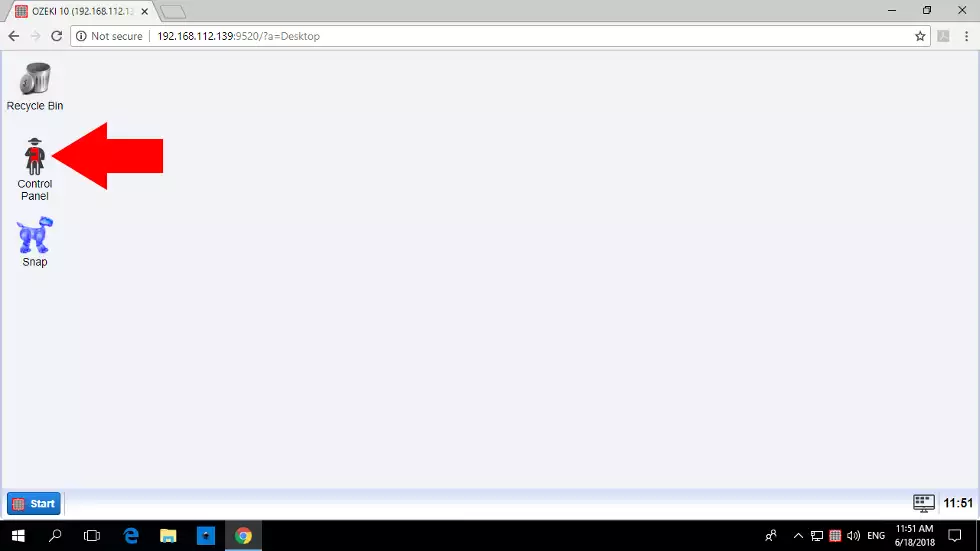
Open your Ozeki 10 from any remote location you wish, but make sure that the ATmega chip is connected to your Ozeki 10 server. Please log in and start the Control Panel by clicking on the red Napoleon icon. Although icons can come and go, but the Control Panel will stay. It is capable to connect all devices with routes. Device management is the best with the Control Panel.
STEP 10: Find your RF Transceiver in the list
Think of the Arduino microcontroller and check if it is connected to your Ozeki 10 server. Since the correct code was uploaded before, the RF transceiver should appear on the list. All detected devices depend only on the installed code and is independent from the modules and wiring. Click on the blue 'Details' button next to the device, so you can test it in real time.
STEP 11: Receive signals from your alarm device
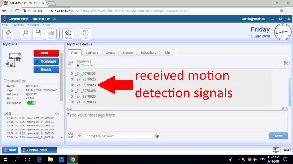
Just move around your motion detector sensor to catch the signals. This chat interface is great to send and receive signals. Keep in mind that if you haven't wired the transmitter, you cannot send messages through this easy to use chat interface. However if you haven't wired a transmitter, you will only receive signals like seen below. You can try remote controllers as well.
STEP 12: Forward it to someone in charge
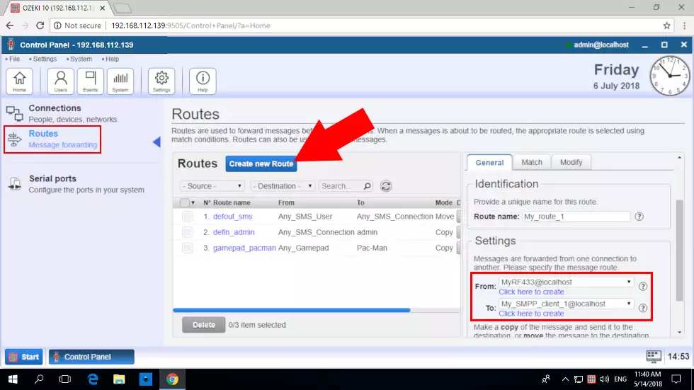
With the Control Panel application you can add routes to Ozeki 10 between two connections. If the example works correctly, you can route incoming messages from the RF receiver to the SMPP SMS Gateway connection. This is a great way to forward signals in SMS messages to any recipient. You can also transmit signals automatically with Ozeki Task Scheduler.
More information
- Controlling a garage door using 433 Mhz Remote
- Plant watering using soil moisture sensor
- Controlling RGB lights using your voice
- Controlling smart devices using a 433 Mhz transmitter
- Controlling door access using RFID, NFC tags
- Scheduled power off
- Creating a 433 Mhz smart alarm system
- Automated shade control
- Creating a VoIP door phone
- Creating an IP camera system
- License plate recognition
- Remote Controlled LED Lightbulbs
