Modbus Function Code 2
Read Discrete Inputs on Modbus
This function code is used for reading from 1 to 2000 contiguous discrete inputs on a remote device. The Request PDU specifies the starting address, i.e. the address of the first input specified, and the number of inputs. In the PDU Discrete Inputs are addressed starting at zero. Therefore Discrete inputs numbered 1-16 are addressed as 0-15.
Request
| Function code | 1 Byte | 0x02 |
| Starting Address | 2 Bytes | 0x0000 to 0xFFFF |
| Quantity of Inputs | 2 Bytes | 1 to 2000 (0x7D0) |
Response
SThe discrete inputs in the response message (Table 2) are packed as one input per bit of the data field. Status is indicated as 1=On; 0=Off. The LSB of the first data byte contains the input addressed in the query. The other inputs follow toward the high order end of this byte, and from low order to high order in subsequent bytes.
If the returned input quantity is not a multiple of eight, the remaining bits in the final data byte will be padded with zeros (toward the high order end of the byte). The Byte Count field specifies the quantity of complete bytes of data.
| Function code | 1 Byte | 0x02 |
| Byte count | 1 Byte | N* |
| Input Status | N* x 1 Byte |
Table 2 - Response structure
Error
| Error code | 1 Byte | 0x82 |
| Exception code | 1 Byte | 01 or 02 or 03 or 04 |
Example
Request
This command is requesting the On/Off (0/1) status of discrete inputs # 10123 to 10150 from the slave device with address 11. Each discrete input is a single bit.
| 0B 02 007A 001C 58B0 |
- 0B: The Slave Address (0B hex = address 11).
- 02: The Function Code 2 (Read Discrete Inputs).
- 007A: The Data Address of the first input to read (00C4 hex = 122, +10001 offset = input #10123).
- 001C: The total number of coils requested (1C hex = 28, inputs 10123 to 10150).
- 58B0: The CRC (Cyclic Redundancy Check) for error checking.
Response
| 0B 02 03 ACDBFB0D 37BC |
- 0B: The Slave Address (0B hex = address 11)
- 02: The Function Code 2 (Read Discrete Inputs)
- 03: The number of data bytes to follow (28 Inputs / 8 bits per byte = 3 bytes plus 4 bits)
- AC: Discrete Inputs 10130 -10123 (1010 1100)
- DB: Discrete Inputs 10138 - 10131 (1101 1011)
- FB: Discrete Inputs 10146 - 10139 (1111 1011)
- 0D: 4 space holders & Discrete Inputs 10150 - 10147 (0000 1101)
- 37BC: The CRC (Cyclic Redundancy Check).
The more significant bits contain the higher Discrete inputs. This shows that input 10123 is Off (0) and 10130 is On (1). Due to the number of inputs requested, the last data field 0D contains the status of only 4 inputs. The four most significant bits in this data field are filled in with zeroes.
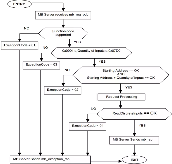
Workflow Diagram for Modbus FC 2

Contents retrieved from
- http://modbus.org/
- http://www.simplymodbus.ca/
