Modbus Function Code 15
Write Multiple Coils on Modbus
This function code is used to force each coil in a sequence of coils to either On or Off in a remote device. The Request PDU specifies the coil references to be forced. Coils are addressed starting at zero. Therefore coil numbered 1 is addressed as 0.
The requested On/Off states are specified by contents of the request data field. A logical '1' in a bit position of the field requests the corresponding output to be On. A logical '0' requests it to be Off.
Request
| Function code | 1 Byte | 0x0F |
| Starting Address | 2 Bytes | 0x0000 to 0xFFFF |
| Quantity of Outputs | 2 Bytes | 0x0001 to 0x07B0 |
| Byte Count | 1 Byte | N* |
| Outputs Value | N* x 1 Byte |
Table 1 - Command structure
Response
The normal response returns the function code, starting address, and quantity of coils forced
| Function code | 1 Byte | 0x0F |
| Starting Address | 2 Bytes | 0x0000 to 0xFFFF |
| Quantity of Outputs | 2 Bytes | 0x0001 to 0x07B0 |
Error
| Error code | 1 Byte | 0x8F |
| Exception code | 1 Byte | 01 or 02 or 03 or 04 |
Example
Request
This command is writing the contents of a series of 9 discrete coils from #28 to #36 to the slave device with address 11.
| 0B 0F 001B 0009 02 4D01 6CA7 |
- 0B: The Slave Address (0B hex = address 11)
- 0F: The Function Code 15 (Write Multiple Coils, 15 = 0F hex)
- 001B: The Data Address of the first coil (001B hex = 27, + 1 offset = coil #28).
- 0009: The number of coils to written (09 hex = 9)
- 02: The number of data bytes to follow (9 Coils = 1 byte + 1 bits + 7 space holders = 2 bytes)
- 4D: Coils 35 - 28 (0100 1101)
- 01: 7 space holders & Coil 36 (0000 0001)
- 6CA7: The CRC (Cyclic Redundancy Check) for error checking.
The more significant bits contain the higher coil variables. This shows that coil 28 is On (1) and 35 is Off (0). Due to the number of coils requested, the last data field contains the status of only 1 coil. The unused bits in the last data byte are filled in with zeroes. These are the space holders.
Response
| 0B 0F 001B 0009 E560 |
- 0B: The Slave Address (0B hex = address 11)
- 0F: The Function Code 15 (Write Multiple Coils, 0F hex = 15)
- 001B: The Data Address of the first coil (001B hex = 27, + 1 offset = coil #28).
- 0009: The number of coils to written (09 hex = 9)
- E560: The CRC (Cyclic Redundancy Check) for error checking.
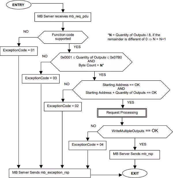
Workflow Diagram for Modbus FC 15

Contents retrieved from
- http://modbus.org/
- http://www.simplymodbus.ca/
