How to connect a Modern Device Wind Sensor to Arudino
Contents
Introduction
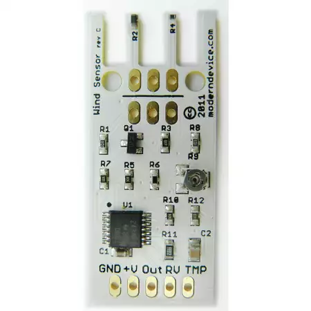
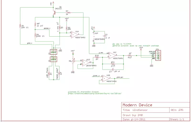
This is an unexpensive wind sensor made for use with electronic projects. The Wind Sensor is a thermal anemometer based on a traditional technique for measuring wind speed.
The technique is called the “hot-wire” technique, and involves heating an element to a constant temperature and then measuring the electrical power that is required to maintain the heated element at temperature as the wind changes.
This measured electrical input is then directly proportional to the square of the wind speed.
The underlying principle that makes the sensor function is the same as the traditional hot-wire technique.
This technique excels at low to medium wind speed, and is the preferred technique for sensing indoor air movement, where the spinning cup anemometers typically seen on weather stations are ineffective.
As an experimenters tool, the sensor is exquisitely sensitive, with a small puff of air being sensed at a distance of 18-24″. Possible applications include human breath detection, room occupancy detection, hvac system monitoring, weather stations and many more.
Specifications
Dimensions: .68″ × 1.590″ × .25″
Supply Voltage: 4 – 10 volts
Supply current: 20 – 40 mA (depending on wind speed)
Output signal: analog, 0 to VCC

Wiring
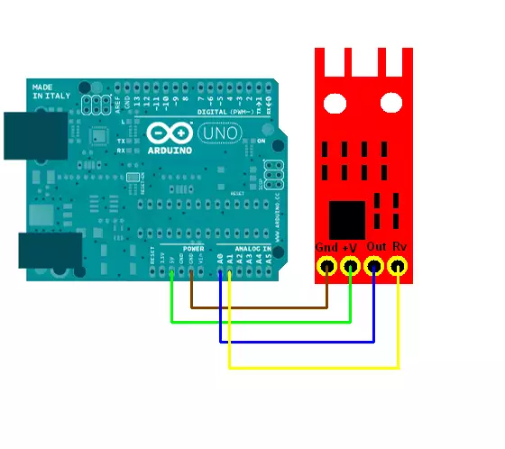
It is quite easy to connect the sensor to Arduino. You will need the Wind sensor, Arduino UNO and wires for wiring. The sensor runs fine between five and ten volts but the Arduino calibration sketch is premised on a regulated five volt supply, so the sketch won’t work at higher voltages.
Put the Ground to GDN pin
Put the VCC to 5V pin
Put the TMP to A0
Put the RV to A1
You can see the circuit schematic in the following picture:

| Wind Sensor Signals | Arduino |
| RV | A1 |
| TMP | A0 |
| GND | GND |
| VCC | 5V |

Calibrating
To start up the sensor need about 10 seconds to thermally stabilize for the best accurracy. You can save power by switching off the hardware to save power. In this 10 seconds the sensing thermistor heats up to operating temperature.
It’s probably also not a good idea to hang the sensor power supply off a microcontroller pin, even an Atmel pin, if best accuracy is a concern, as the sensor draws a bit of current (~25 mA) and the current will also fluctuate with wind speed.
The Wind Sensor includes a small trimpot that is used to calibrate the sensor for zero wind. Calibration is simple. Simply put a glass over the sensor to block any breeze and adjust the pot for the desired zero level.
We calibrate the sensors roughly for .5V of output at zero wind with a six volt supply, but you are free to calibrate as desired. A lower calibration point, say .2 V will result in a little more sensing capability at the high end.
Using a higher voltage supply will require recalibration. Do not use supplies higher than about 10 volts.
Example code
#define analogPinForRV    1   //change to pins you the analog pins are using
#define analogPinForTMP   0

// to calibrate your sensor, put a glass over it, but the sensor should not be
// touching the desktop surface however.
// adjust the zeroWindAdjustment until your sensor reads about zero with the glass over it.

const float zeroWindAdjustment =  .2;
//negative numbers yield smaller wind speeds and vice versa.

int TMP_Therm_ADunits;  //temp termistor value from wind sensor
float RV_Wind_ADunits;  //RV output from wind sensor
float RV_Wind_Volts;
unsigned long lastMillis;
int TempCtimes100;
float zeroWind_ADunits;
float zeroWind_volts;
float WindSpeed_MPH;

void setup() {

 Serial.begin(57600);   // faster printing to get a bit better throughput on extended info
 // remember to change your serial monitor

 Serial.println("start");
 // put your setup code here, to run once:

 //   Uncomment the three lines below to reset the analog pins A2 & A3
 //   This is code from the Modern Device temp sensor (not required)
 pinMode(A2, INPUT);        // GND pin
 pinMode(A3, INPUT);        // VCC pin
 digitalWrite(A3, LOW);     // turn off pullups

}

void loop() {


 if (millis() - lastMillis > 200){      // read every 200 ms - printing slows this down further

    TMP_Therm_ADunits = analogRead(analogPinForTMP);
    RV_Wind_ADunits = analogRead(analogPinForRV);
    RV_Wind_Volts = (RV_Wind_ADunits *  0.0048828125);

    // these are all derived from regressions from raw data as such
    // they depend on a lot of experimental factors
    // such as accuracy of temp sensors, and voltage at the actual wind sensor
    // (wire losses) which were unaccounted for.
    TempCtimes100 = (0.005 *((float)TMP_Therm_ADunits * (float)TMP_Therm_ADunits))
    					- (16.862 * (float)TMP_Therm_ADunits) + 9075.4;

    zeroWind_ADunits = -0.0006*((float)TMP_Therm_ADunits * (float)TMP_Therm_ADunits)
    					+ 1.0727 * (float)TMP_Therm_ADunits + 47.172;  //  13.0C  553  482.39

    zeroWind_volts = (zeroWind_ADunits * 0.0048828125) - zeroWindAdjustment;

    // This from a regression from data in the form of
    // Vraw = V0 + b * WindSpeed ^ c
    // V0 is zero wind at a particular temperature
    // The constants b and c were determined by some Excel wrangling with the solver.

   WindSpeed_MPH =  pow(((RV_Wind_Volts - zeroWind_volts) /.2300) , 2.7265);

    Serial.print("  TMP volts ");
    Serial.print(TMP_Therm_ADunits * 0.0048828125);

    Serial.print(" RV volts ");
    Serial.print((float)RV_Wind_Volts);

    Serial.print("\t  TempC*100 ");
    Serial.print(TempCtimes100 );

    Serial.print("   ZeroWind volts ");
    Serial.print(zeroWind_volts);

    Serial.print("   WindSpeed MPH ");
    Serial.println((float)WindSpeed_MPH);
    lastMillis = millis();
 }

}
