Creating an USB temperature sensor
Connect an USB temperature sensor for data acquisition, which is a great way to collect temperature and humidity data from your environment, so you can share the data or further analyse it. You need a few devices found in this tutorial. To wire it, you will need a microcontroller and a DHT sensor. Upload the open source codes to your microcontroller, which can be found on your Ozeki 10's server machine. The tutorial shows how simply you can plug your USB temperature sensor to the Ozeki 10 server and read data.
STEP 1: What you need... you can buy these parts on ebay
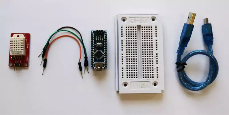
If you are a hobby developer, look around your place to find the parts, but if you are new to microcontroller programming, you should start by adding some devices in your shopping cart. You will need a DHT11 or DHT22 sensor, 3 jumper wires, an Arduino with USB cable and a breadboard. DHT22 is highly advised since it has a bigger range and is highly accurate. Look around on ebay to find the parts. Type them in ebay search.
STEP 2: Wiring diagram
After acquiring the parts, please connect them accordingly to the wiring diagram below. It can be powered through the 5V output of the Arduino, which is connected with a red wire and the GND pin of the Arduino connected with a black wire. These colors are international standards. Use any color of wire to connect the DHT sensor's data pin to your Arduino's D2 pin. You can modify the pin through the Arduino IDE, although D2 is default.
STEP 3: Connecting the sensor
Connect the microcontroller to the DHT sensor with the help of the wiring diagram. Use the 3 jumper wires you have purchased from ebay and connect the mini USB cable to your Arduino device. Check if the other side of the cable can be plugged into your machine. Plug it in. Your computer will detect it on the serial communication COM port to receive or forward data.
STEP 4: Installing Ozeki 10
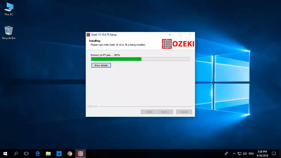
Install Ozeki 10 on your operating system which can be a Windows, Linux, Raspberry Pi, Asus TinkerOS or Android. The screenshot below is created on Windows 10, although Windows 7 is supported too. Download the installer package for your OS at http://www.ozeki.hu/index.php?owpn=231 You can find tutorials for each OS in this book or on www.ozeki.hu
STEP 5: Installing Arduino IDE
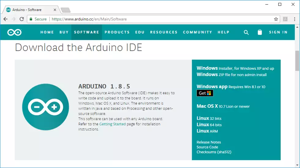
The second software required is the Arduino IDE. It is really important to download it from the following trusted source at https://www.arduino.cc/ After downloaded you can easily install any Arduino C++ codes to the ATmega microcontroller, which is the chip integrated on the Arduino boards.
STEP 6: Formatting EEPROM
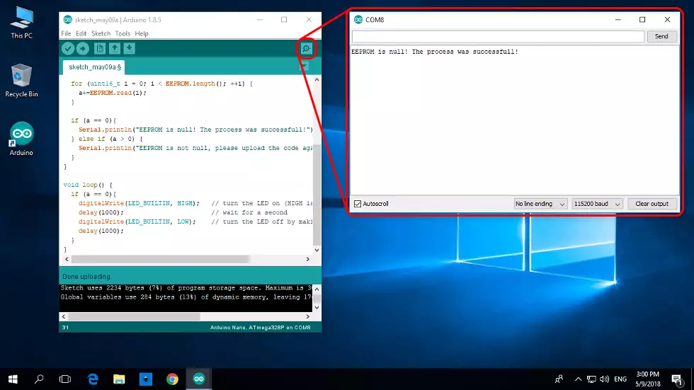
Start the Arduino IDE to upload the first code which you can copy paste from http://www.ozeki.hu/index.php?owpn=3110 It wipes the Arduino's EEPROM, which is important for the Ozeki DHT device to install. It is highly advised to clear the EEPROM, before uploading any Ozeki device.
STEP 7: Uploading the code
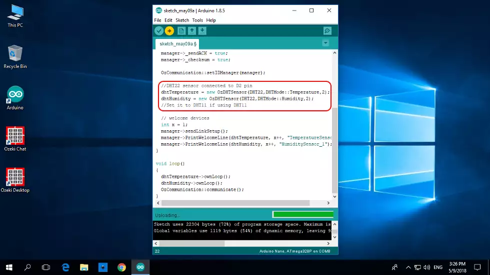
After downloading the Ozeki 10, the open source libraries will be install under ...Documents\Arduino\libraries\ These codes are tested on Arduino Mega, Nano or Uno, but they can be rewritten and used on any other microcontroller board. Please download and run the DHT specific codes:C:\Users\User\Documents\Arduino\libraries\OzDHTController\OzDHTControllerTestKeep in mind to modify code to DHT22. See it in the picture below.
STEP 8: Login to Ozeki and start Control Panel
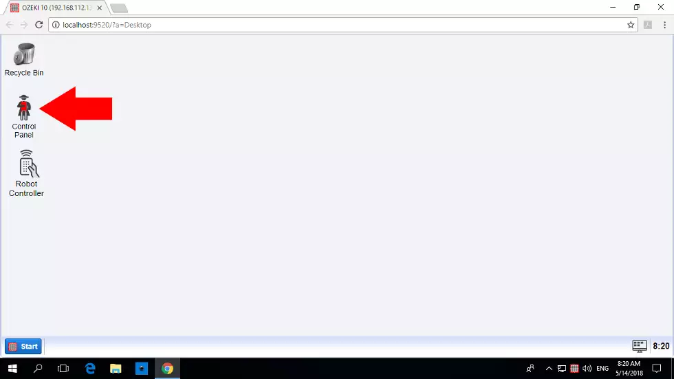
Finally, you can start the Ozeki 10 server and log in through your webbrowser. You can easily do this with the username and password pair you have provided during Ozeki 10's installation. Click 'OK' and you'll see the desktop GUI like on the screenshot below. To continue on, please open the Control Panel, which is the place to manage your connections. In this tutorial the Control Panel will be used for measuring temperature. Storing sensor data in SQL database will be discussed in another tutorial. The great thing is that if the code was successfully uploaded to the Arduino, Ozeki 10 can autoconnect to it, which you can set in the next step.
STEP 9: Setup automatic serial port connection in the Control Panel
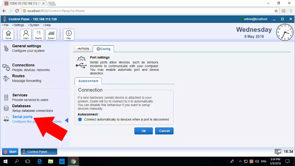
You will not see the two DHT sensor connections appear on the list of connections. This is why you have to turn ON autoconnect. Click on 'Serial Ports' on the vertical toolbar and you will see the detected COM ports. If a port is green, it is connected to Ozeki 10 if it is red then the port is not connected, yet, so click on the 'Config' tab with the cog icon and tick the 'Autoconnect' checkbox and click 'Ok' like on the picture below.
STEP 10: Connect the sensor
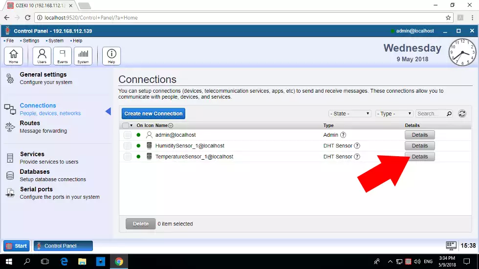
After setting Autoconnect, go back to the connection list by clicking 'Connections' on the vertical toolbar. Please refresh with the round refresh symbol if you cannot see the DHT sensor connections. You should see two new connections appear. The first is the humidity sensor and the second is the temperature sensor. The green LED on the GUI besides them shows if the connection can be reached for communication.
STEP 11: Open details page
If you see both connections, you can probably hardly wait to test them. Now you will see how to test the temperature sensor. Please click the blue 'Details' button next to the temperature sensor, but you can do the same with the humidity sensor if you prefer to try it first. Find yourself on the 'Test' tabpage. By clicking 'Measure' you can get sensor data events.
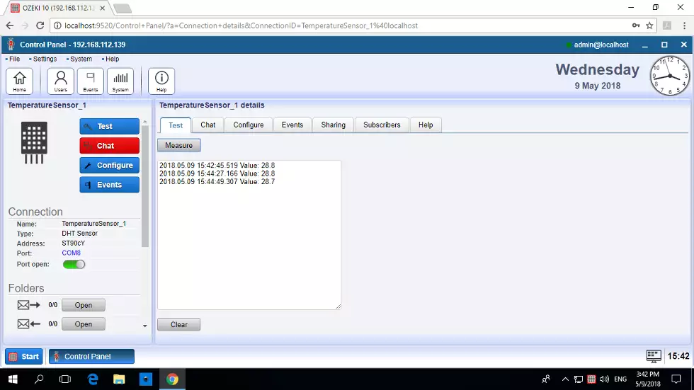
STEP 12: View configuration
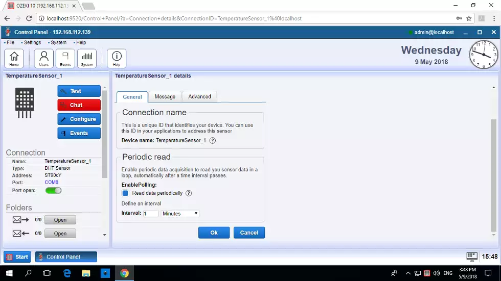
Switch to the 'Configure' tabpage right to the 'Test' tabpage. Here you can configure your the 'Periodic read'. You can set the time period in a preferred unit and turn it on with the checkbox. Go back to the 'Test' page to see all periodic readings. The most important benefit of it is that you can periodicly store sensor data in your database. The next guide will lead you through it.
- EEPROM format (http://www.ozeki.hu/index.php?owpn=3110)
- DHT connection (http://www.ozeki.hu/index.php?owpn=2986)
- DHT to Arduino Mega (http://www.ozeki.hu/index.php?owpn=3003)
- DHT to Arduino Nano (http://www.ozeki.hu/index.php?owpn=3004)
- DHT to Arduino Uno (http://www.ozeki.hu/index.php?owpn=3005)
- Request DHT data through chat (http://www.ozeki.hu/index.php?owpn=5633)
- The protocol between the DHT sensor and Ozeki 10 (http://www.ozeki.hu/index.php?owpn=3115)
