Ozeki NFC Host
The Ozeki NFC Host is a modified Arduino Nano, that can be a host of two RC522 and one PN532 NFC modules. This is an open source board, with all the files needed for manufacturing. You may also freely modify the design.
The Ozeki NFC Host contains an ATmega328P microcontroller so you can program it just like an Arduino Nano using the Arduino IDE environment. It has a micro USB port, which is compatible with mobile phone USB cables. It is better then using an Arduino Nano, because it is more compact solution, since the NFC readers can directly connect to the host. It also has standard mounting holes for M2 screws.

You can also connect buttons, switches, feedback leds to it for specialised needs from A0 to A7 pins. These pins can be used in both analog or digital mode. Leds can show you whether a card is accepted or refused or if one of the NFC module is malfunctioning. You can connect buttons for opening doors from the inside. The A4 (SDA) and A5 (SCL) are I2C pins. They can be used for connecting one PN532 NFC module or other I2C devices. Your imagination is the limit how to use these 8 pins.


|
Download files for manufacturing
|
|
Datasheets
|
Ozeki NFC Host
Specifications:
- IC: ATmega328P
- Clock Speed: 16 MHz
- Flash Memory: 32 KB
- SRAM: 2 KB
- EEPROM: 1 KB
- USB support provided by a CH340G USB to serial chip:
- Micro USB (compatible with mobile phone USB cables)
- Connection to the Ozeki HUB Controller
- ICSP (In-Circuit Serial Programming)
- Power supply from USB (5V)
- A maximum of 3 NFC modules can be connected to it:
- RC522 (up to two modules, SPI,
own 3.3V power supply for both) - PN532 (one module, I2C)
- RC522 (up to two modules, SPI,
- 500mA resettable fuse
- Status LEDs: power, TX, RX, D13
- Can be screwed on an Ozeki Matrix Board
- Product dimensions:
2.40in.[60.96mm]×0.80in.[20.32mm]
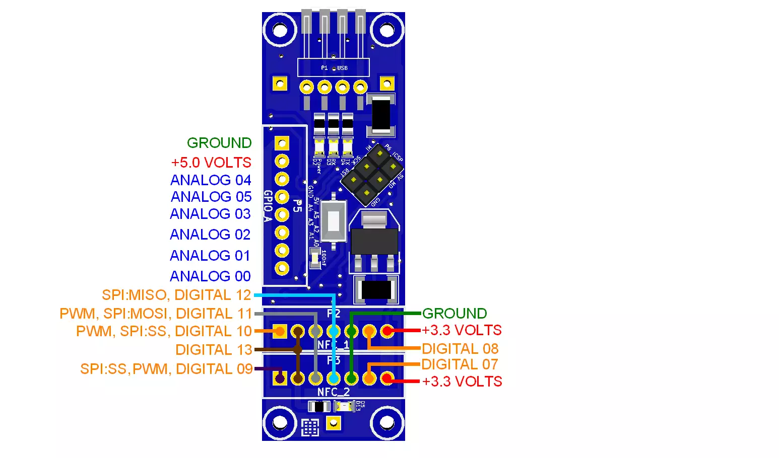
Pinout of the Ozeki NFC Host:

RC522 and PN532 NFC modules
Features:
- Longest effective communication distance of 6 cm (Mifare1 card)
- Can be used for 13.56MHz non-contact communication
- Two-way transmission rate up to 424kbit/s.
- Compatible with ISO14443 Type A and Type B standards
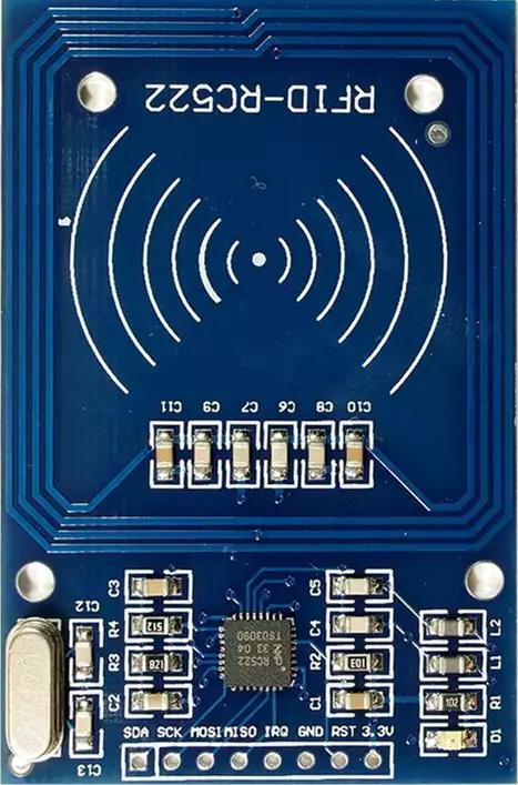
RC522 NFC module
Specifications:
- IC: NXP MFRC522
- Interface: SPI
- Cards supported: Mifare1 S50, Mifare1 S70, Mifare UltraLight, Mifare Pro, Mifare Desfire
- Operating current: 13-26mA/DC 3.3V
- Idle current: 10-13mA/DC 3.3V
- Sleep current: <80uA
- Peak current: <30mA
- Operating Frequency: 13.56MHz
- Product size: 40mm×60mm
- Environmental Operating temperature: -20-80 degrees Celsius
- Environmental Storage Temperature: -40-85 degrees Celsius
- Relative humidity: 5% -95%
- Data transfer rate (SPI): maximum 10Mbit/s
- Radiotransmission rate: maximum 424kbit/s
- Radiotransmission frequency: 13.56MHz
- Max Supply Current: 150mA
- Working Current(Standby Mode): 100mA
- Working Current(Write Mode): 120mA
- Working Current(Read Mode): 120mA
- Status LED: power
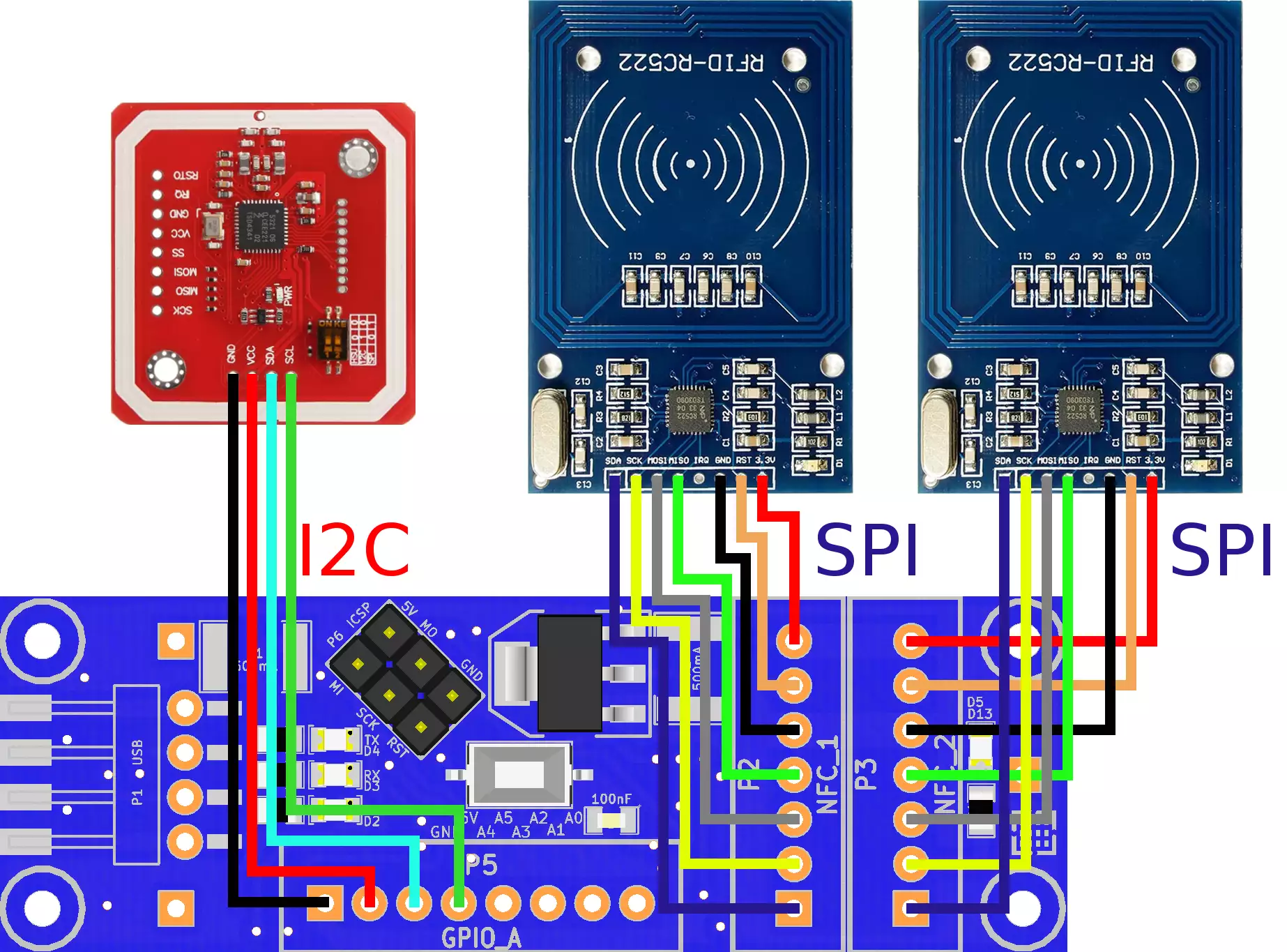
The pinout for the RC522 NFC connections:
| RC522 | SDA | SCK | MOSI | MISO | IRQ | GND | RST | Supply Voltage |
| NFC1 | D10 | D13 | D11 | D12 | - | GND | D8 | 3.3V |
| NFC2 | D9 | D13 | D11 | D12 | - | GND | D7 | 3.3V |

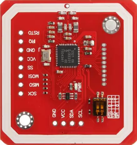
PN532 NFC module
Specifications:
- IC: NXP PN532
- Interface: SPI, I2C and HSU (High Speed UART)
- Card types supported:
- Mifare 1k, 4k, Ultralight, and DesFire cards
- ISO/IEC 14443-4 cards such as CD97BX, CD light, Desfire, P5CN072 (SMX)
- Innovision Jewel cards such as IRT5001 card
- FeliCa cards such as RCS_860 and RCS_854
- Operating voltage: DC 3.3V
- Power Supply Voltage: 3.3V-5V
- Operating Frequency: 13.56MHz
- Product size: 40.4mm×42.7mm
- Environmental Operating temperature: -30-85 degrees Celsius
- Environmental Storage Temperature: -55-150 degrees Celsius
- Data transfer rate (SPI): maximum 10Mbit/s
- Data transfer rate (I2C): maximum 3.2Mbit/s
- Radiotransmission rate: maximum 424kbit/s
- Radiotransmission frequency: 13.56MHz
- Max Supply Current: 150mA
- Working Current(Standby Mode): 100mA
- Working Current(Write Mode): 120mA
- Working Current(Read Mode): 120mA
- Status LED: power
The pinout for the NXP PN532 NFC connections:
| PN532 | GND | Supply Voltage | SDA | SCL |
| NFC3 | GND | 5V | A4 | A5 |

Wiring:
Connect the NFC card readers to the Ozeki NFC Host Module as shown below. Before wiring the NFC boards to your Ozeki NFC Host Module we suggest to solder a JST header strip to the following 7 pin count connector of the MFRC522 and a minimum of 4 pin JST header strip for the PN532, as you can see in the image above.

Program codes
Connects two RC522 modules
Before starting, you need to download the MFRC522 library from the Arduino IDE top menu: Sketch/Import library.../Add library... and type 'MFRC522' in the search.
Now you can connect a maximum of two RC522 modules to your Ozeki NFC Host and upload this code to the host. Make sure that the RC522 modules are in safe distance from eachother to work properly. Place your RFID chip close to one of the module's surface and you should read the value contained on the chip from the serial port.
Downloadable code:
NFC_Host_ExampleCode_RC522.zip
Video 2 - Reading NFC keycards with two RC522 modules by using the code below
Source Code 1 - Arduino example code for reading two RC522 modules#include <SPI.h> #include <MFRC522.h> #define SS_1_PIN 10 #define SS_2_PIN 9 #define RST_PIN_1 8 #define RST_PIN_2 7 MFRC522 reader_0(SS_1_PIN, RST_PIN_1); MFRC522 reader_1(SS_2_PIN, RST_PIN_2); MFRC522::MIFARE_Key key; byte nuidPICC[4]; void setup() { Serial.begin(115200); SPI.begin(); reader_0.PCD_Init(); reader_1.PCD_Init(); Serial.println("Now you can scan the RFID chips."); } void loop() { NFC_0(); NFC_1(); } void NFC_0() { for (byte i = 0; i < 6; i++) { key.keyByte[i] = 0xFF; } if ( ! reader_0.PICC_IsNewCardPresent()) return; if ( !reader_0.PICC_ReadCardSerial()) return; for (byte i = 0; i < 4; i++) { nuidPICC[i] = reader_0.uid.uidByte[i]; } Serial.print(F("READER_0: ")); printDec(reader_0.uid.uidByte, reader_0.uid.size); Serial.println(); reader_0.PICC_HaltA(); reader_0.PCD_StopCrypto1(); } void NFC_1(){ for (byte i = 0; i < 6; i++) { key.keyByte[i] = 0xFF; } if ( ! reader_1.PICC_IsNewCardPresent()) return; if ( ! reader_1.PICC_ReadCardSerial()) return; for (byte i = 0; i < 4; i++) { nuidPICC[i] = reader_1.uid.uidByte[i]; } Serial.print(F("READER_1: ")); printDec(reader_1.uid.uidByte, reader_1.uid.size); Serial.println(); reader_1.PICC_HaltA(); reader_1.PCD_StopCrypto1(); } void printDec(byte *buffer, byte bufferSize) { for (byte i = 0; i < bufferSize; i++) { Serial.print(buffer[i] < 0x10 ? " 0" : " "); Serial.print(buffer[i], DEC); } }
Other modules
All of the Ozeki Processing Modules have ATmega328P or ATmega2560 microcontrollers integrated. Ozeki Modules can be connected to eachother like pieces of blocks. The connection is provided through USB to each module. They have M2 screw holes to give you an option to screw them on an Ozeki Matrix Board.
AutoConnect Link
If Ozeki 10 is running on your computer (such as on a Raspberry Pi) and you have plugged a microcontroller to it than Ozeki can be set to find serial devices on windows/linux and place them into a connection list so you can interact and control them through the software GUI.
