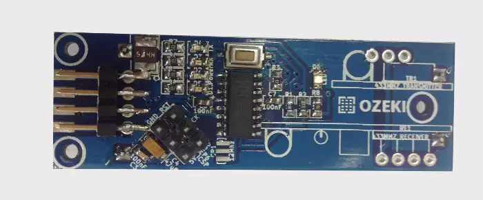
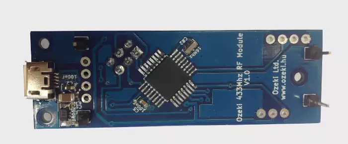
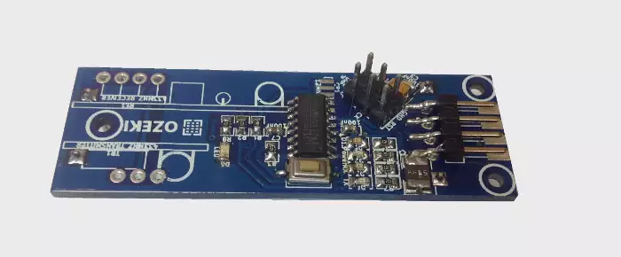
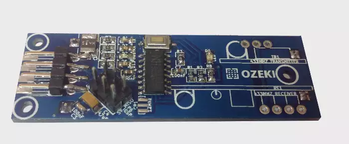
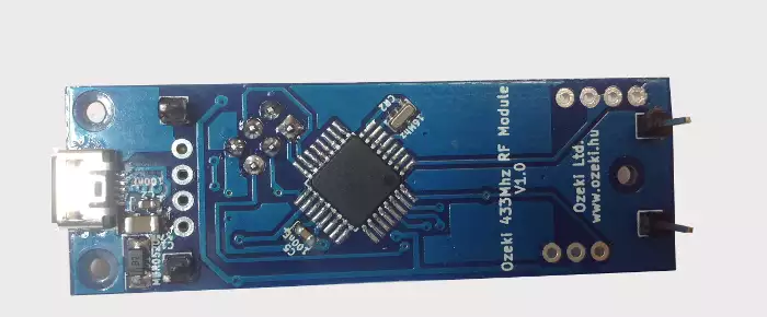
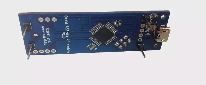
Ozeki 433 Mhz RF Module
The is a modified Arduino Nano. You can directly plug 433Mhz RF transmitter/receiver modules to it. This is an open source board, with all the files needed for manufacturing. You may also freely modify the design.

You can use the 433 MHz communication with wireless infrared motion sensors and RF remote controllers:
Video 1 - Shows how to upload code to

The contains an ATmega328P microcontroller so you can program it just like an Arduino Nano using the Arduino IDE environment. It has a micro USB port, which is compatible with mobile phone USB cables. It was designed to make it easy to solder in the RF transmitter and receiver parts, and it has standard mounting holes for M2 screws. It is better then using an Arduino Nano, because it is more compact solution, since the RF transmitter and receiver are soldered directly to the board.
|
Download files for manufacturing
|
|
Datasheets
|
Specifications
- IC: ATmega328P
- Clock Speed: 16 MHz
- Flash Memory: 32 KB
- SRAM: 2 KB
- EEPROM: 1 KB
- USB support provided by a CH340G USB to serial chip:
- Micro USB (compatible with mobile phone USB cables)
- Connection to the Ozeki HUB Controller
- Power supply from USB (5V)
- 500mA resettable fuse
- Status LEDs: power, TX, RX, D13, D10
- Can be screwed on an Ozeki Matrix Board
- Product dimensions:
2.40in.[60.96mm]×0.80in.[20.32mm] - Transmitter parameters:
- Launch distance: 20-200 meters (different voltage, different results)
- Operating voltage: 3.5-12V
- Operating mode: AM
- Transfer rate: 4KB/s
- Transmitting power: 10mW
- Transmitting frequency: 433.92 Mhz
- Transmitter pin: D2
- Receiver parameters:
- Operating voltage: 5V
- Quiescent Current: 4mA
- Receiver sensitivity: -105DB
- Receiving frequency: 433.92 Mhz
- Reciever pin: D3
Pinout of the :

Program codes
Sends and receives 433 MHz signals
Simple test
To simply test this code upload it to an Ozeki 433Mhz RF module and send RF signals to it from outside sources. Here are a few RF sources you can find:
- Wireless infrared motion sensor
- RF remote controller
Test it by sending signals from one Ozeki RF module to another
To fully test out this code you will need two Ozeki 433Mhz RF modules and upload this code to both modules. One will be the transmitter and the other will be the receiver. The transmitter can transmit any integer value (-32,768 to 32,767). You just need to simply write in the number and press Enter to send. The other one will show the signals arrived on it's serial screen. To communicate with 2 serial ports at the same time you should use multiple Arduino IDEs or use our sophisticately designed software for parallel serial communication: Ozeki Terminal.
Downloadable code:
RF_Module_ExampleCode.zipSource Code 1 - Arduino example for 433 MHz signal communication Video 1 - Watch video to see the code above at work#include <RCSwitch.h> RCSwitch myTransmitterSwitch = RCSwitch(); //repeats transmission 10 times //uses protocol 1 RCSwitch myReceiverSwitch = RCSwitch(); //repeats transmission 10 times //uses protocol 1 char inputString[256]; void setup() { Serial.begin(115200); myTransmitterSwitch.enableTransmit(2); // Transmitter is connected to Arduino Pin D2 myReceiverSwitch.enableReceive(1); // Receiver on interrupt 1 => that is pin D3 Serial.println("Please type any int (-32,768 to 32,767) and press Enter."); Serial.println("If data is received the program automatically writes it out."); } void loop() { if(Serial.available()){ delay(1); ReadLine(); myTransmitterSwitch.send(atoi(inputString), 24); //Transmit signal Serial.println(""); Serial.print(atoi(inputString)); Serial.println(" has been sent."); if (myReceiverSwitch.available() && (myReceiverSwitch.getReceivedValue() == atoi(inputString)) ) myReceiverSwitch.resetAvailable(); //removes transmitted_value from received for(int i=0; i<256; i++) inputString[i] = NULL; } if (myReceiverSwitch.available()) { //Signal received int value = myReceiverSwitch.getReceivedValue(); if (value == 0) { Serial.println("Unknown encoding"); } else { Serial.print("Received number: "); Serial.println( value ); } myReceiverSwitch.resetAvailable(); } } void ReadLine() { for(int i=0; i<256; i++) inputString[i] = NULL; int i=0; while (Serial.available()) { inputString[i] = (char)Serial.read(); if (inputString[i] == '\n') { break; } i++; } }
Other modules
All of the Ozeki Processing Modules have ATmega328P or ATmega2560 microcontrollers integrated. Ozeki Modules can be connected to eachother like pieces of blocks. The connection is provided through USB to each module. They have M2 screw holes to give you an option to screw them on an Ozeki Matrix Board.
AutoConnect Link
If Ozeki 10 is running on your computer (such as on a Raspberry Pi) and you have plugged a microcontroller to it than Ozeki can be set to find serial devices on windows/linux and place them into a connection list so you can interact and control them through the software GUI.